Convenient short-circuit grounding device
A technology of grounding device and connecting device, which is applied in the direction of circuit, connection, conductive connection, etc., can solve the problems of not being able to easily judge the wires, increase the difficulty of operation, and not easy to clamp the wires, etc., and achieve easy and convenient work, simple and convenient operation, and a degree of automation high effect
- Summary
- Abstract
- Description
- Claims
- Application Information
AI Technical Summary
Problems solved by technology
Method used
Image
Examples
Embodiment 1
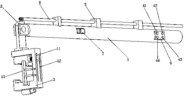
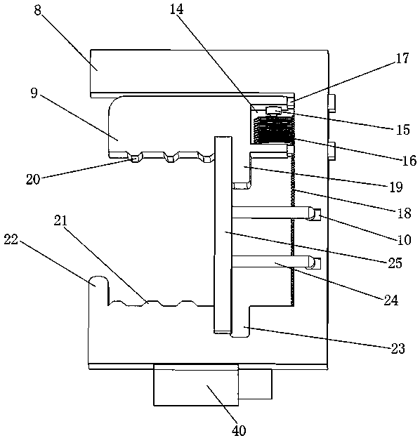
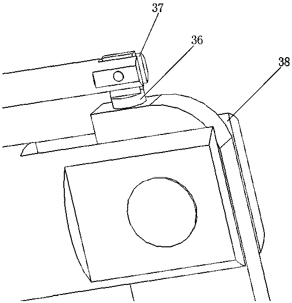
[0027]A short-circuit grounding device that is convenient to use, including a grip bar 1, a chuck connection device 2, a chuck 3, a connecting adjustment rod 4, a support cable device 34 and an electric control system; the tail of the grip bar 1 is provided with an indicator light and The button area 6 is provided with a groove one 28 in the middle, and a block device 7 is arranged in the groove one 28; the end of the handle bar 1 is connected to the clamp connecting device 2; the top of the clamp connecting device 2 is provided with Protrusion 36, the protrusion 36 is connected to the adjustment long rod 4; the collet 3 is fixed under the collet connection device 2; the collet 3 includes a clamp seat 8, a movable clamp block 9 and a clamping induction device 13; The right side of the movable clamp block 9 is provided with a groove two 14; a motor 15 is fixed on the inner side upper surface of the groove two 14; the rotor of the motor 15 is connected with a threaded sliding blo...
Embodiment 2
[0034] The second embodiment is basically the same in structure and principle as the first embodiment, except that the block device 7 includes a block 29 , a hand protrusion 30 and a spring 2 31 ; the hand protrusion 30 is arranged on the top of the block 29 . Through the handle protrusion 30, the locking block 29 can be easily turned up.
Embodiment 3
[0036] The structure and principle of this embodiment 3 are basically the same as that of embodiment 1, the difference is that the clamping tooth 20 is provided on the clamping surface of the movable clamp block 9, and the clamping tooth 20 is provided on the clamping surface of the clamp base 8. Two clamping teeth 21. The protrusions and depressions of the clamping tooth one 20 correspond to the depressions and protrusions of the clamping tooth two 21 one by one, so that the clamping of the wire is more stable.
PUM
 Abstract
Description
Claims
Application Information
 - R&D Engineer
- R&D Manager
- IP Professional
- Industry Leading Data Capabilities
- Powerful AI technology
- Patent DNA Extraction
Browse by: Latest US Patents, China's latest patents, Technical Efficacy Thesaurus, Application Domain, Technology Topic, Popular Technical Reports.
© 2024 PatSnap. All rights reserved.Legal|Privacy policy|Modern Slavery Act Transparency Statement|Sitemap|About US| Contact US: help@patsnap.com


