
Centrifugal barrel polishing mechanical pre-polishing method for copper cavity substrate

A technology of roller polishing and substrate, applied in polishing compositions containing abrasives, grinding/polishing equipment, machine tools for surface polishing, etc., can solve the problems of affecting the quality of vacuum coating, unsatisfactory effect, low repeatability, etc.

Active Publication Date: 2021-01-19
INST OF HIGH ENERGY PHYSICS CHINESE ACADEMY OF SCI
View PDF5 Cites 3 Cited by
  • Summary
  • Abstract
  • Description
  • Claims
  • Application Information

AI Technical Summary

Problems solved by technology

Thereby what adopt in formula is the particle size of 3 μm, but do not give very detailed comparative study of other particle sizes, and before the present invention, we carry out the application research to JLAB formula, find that the effect of the third step is really unsatisfactory, can't get Ideal pre-polishing effect, which will directly affect the subsequent chemical polishing, and then affect the quality of vacuum coating
Therefore, with this formula, the repeatability is not high

Method used


Image

  • Centrifugal barrel polishing mechanical pre-polishing method for copper cavity substrate
  • Centrifugal barrel polishing mechanical pre-polishing method for copper cavity substrate
  • Centrifugal barrel polishing mechanical pre-polishing method for copper cavity substrate

Examples


Embodiment Construction

[0039] The present invention will be described in further detail below in conjunction with the accompanying drawings.

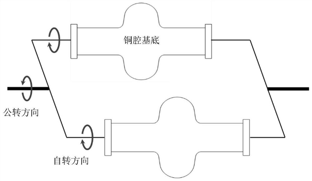
[0040] The present invention aims to explore a set of centrifugal tumbling and polishing formula applied to the base of copper cavity, which is convenient for subsequent chemical polishing or electropolishing, so as to carry out vacuum coating. The principle diagram of centrifugal rolling and throwing is attached figure 1As shown, including the 1.3GHz ellipsoidal copper cavity substrate to be polished, the directions of rotation and revolution in centrifugal tumbling are completely opposite. Under the joint action of rotation and revolution, the centrifugal force on the abrasive is perpendicular to the cavity wall (normal direction), and the abrasive and the cavity wall move relative to each other in a tangential direction, thereby producing a polishing effect on the cavity wall. Abrasive selection, dosage, time, temperature and other factors directly deter...


PUM


Abstract

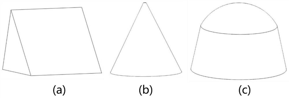
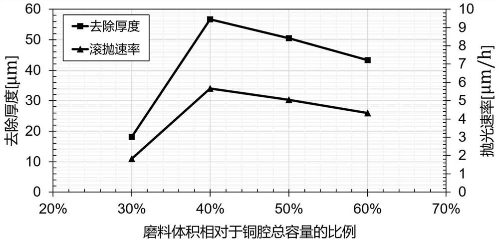
The invention discloses a centrifugal barrel polishing mechanical pre-polishing method for a copper cavity substrate. The method comprises the following steps of 1) selecting oblique-triangle-shaped corundum and a grinding material, mixing the oblique-triangle-shaped corundum with diluted grinding fluid, pouring the mixture into a copper cavity, and carrying out primary barrel polishing on the copper cavity substrate for 40-50 hours by adopting a centrifugal barrel polishing method; 2) selecting cone-shaped resin as a grinding material, mixing the cone-shaped resin with diluted grinding liquid, pouring the mixture into the copper cavity, and carrying out secondary barrel polishing on the copper cavity substrate for 25-30 hours; 3) selecting bullet-shaped resin as a grinding material, mixing the bullet-shaped resin with diluted grinding fluid, pouring the mixture into the copper cavity, and carrying out tertiary barrel polishing on the copper cavity substrate for 25-30 hours; and 4) selecting corncobs as a grinding material, mixing the corncobs with a metal polishing paste, pouring the mixture into the copper cavity, and carrying out quaternary barrel polishing on the copper cavitysubstrate; wherein the volume of the grinding material selected each time accounts for 38-42% of the total volume of the copper cavity, and as for the usage amount of the metal polishing paste, the volume of the metal polishing paste accounts for 1% of the volume of the corncobs.

Description

technical field [0001] The invention relates to a centrifugal rolling and polishing mechanical pre-polishing method, in particular to a centrifugal rolling and polishing mechanical pre-polishing method for vacuum magnetron sputtering niobium-plated copper cavity substrates. Background technique [0002] The full name of the accelerator is "charged particle accelerator", which is a device that artificially generates high-energy charged particle beams. It uses a certain form of electromagnetic field to accelerate charged particles such as electrons, protons, and light and heavy ions, so that their speed reaches a level close to the speed of light. This kind of particle beam with relatively high energy is an important tool for people to change the atomic nucleus, study "elementary particles", and understand the deep structure of matter. Particle accelerator is a complex high-tech engineering equipment, mainly composed of four basic parts: particle source, vacuum acceleration c...

Claims


Application Information

Patent Timeline
IPC IPC(8): B24B31/03C09K3/14C09G1/02
CPCB24B31/03C09G1/02C09K3/1463
Inventor 杨馥羽张沛李中泉戴劲
Owner INST OF HIGH ENERGY PHYSICS CHINESE ACADEMY OF SCI
Learn More