Efficient all-weather air temperature vaporizer
An all-weather, vaporizer technology, applied in non-pressure vessels, container filling methods, container discharge methods, etc., can solve the problems that the output gas temperature cannot be guaranteed to meet the equipment requirements, the outlet gas temperature cannot be controlled in real time, and the vaporizer is bulky, etc. Achieve the effect of being conducive to promotion and use, simple structure and low cost
- Summary
- Abstract
- Description
- Claims
- Application Information
AI Technical Summary
Problems solved by technology
Method used
Image
Examples
Embodiment 1
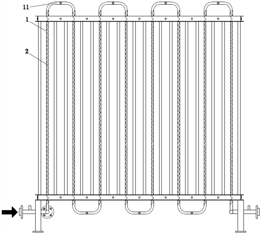
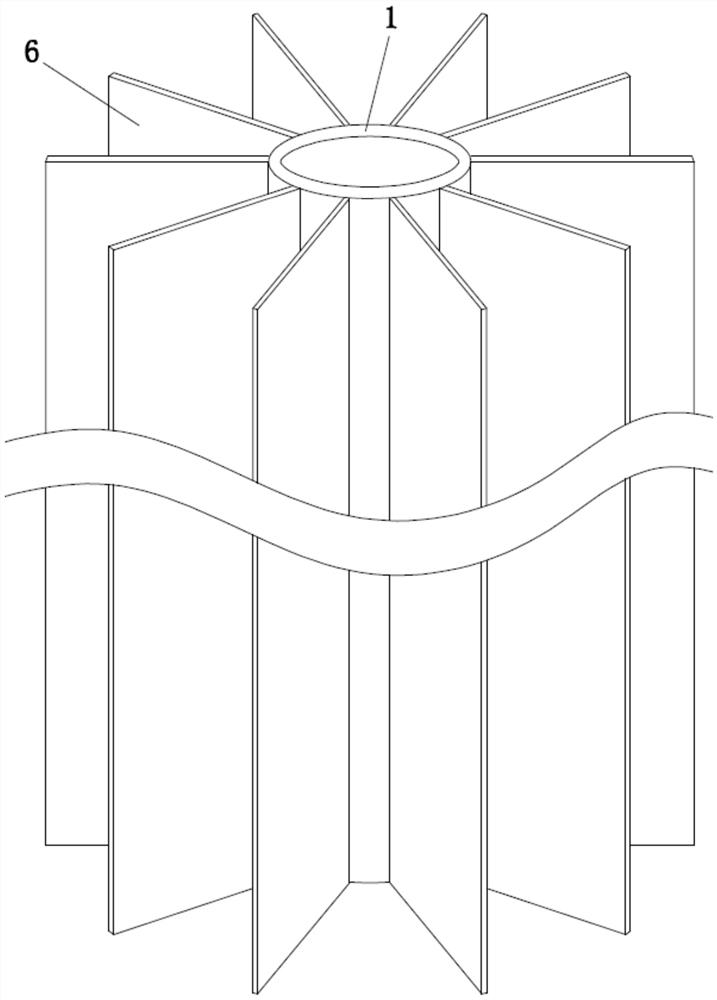
[0029] Such as figure 1 and figure 2 As shown in , the high-efficiency all-weather air-temperature evaporator described in Embodiment 1 of the present invention includes a finned tube 1 and a multiplier 2, and the multiplier 2 is arranged in the finned tube 1 along the axial direction. The multiplier 2 has a spiral shape, and its material can be any metal such as steel, iron, copper, aluminum, or their alloys or non-metal, so that the inside of the finned tube 1 forms a spiral-shaped flow guide channel. Wherein, the multiplier 2 is coaxial with the finned tube 1, and its outer edge is in direct contact with the inner tube wall of the finned tube 1; the specific structure can be: between the ends of the finned tube 1 Connected by the connecting pipe 11, the multiplier 2 is arranged inside the finned tube 1, and the outside of the finned tube 1 is the fins 6 distributed in the circumferential direction, and the fins 6 are used to exchange the low temperature in the finned tube...
Embodiment 2
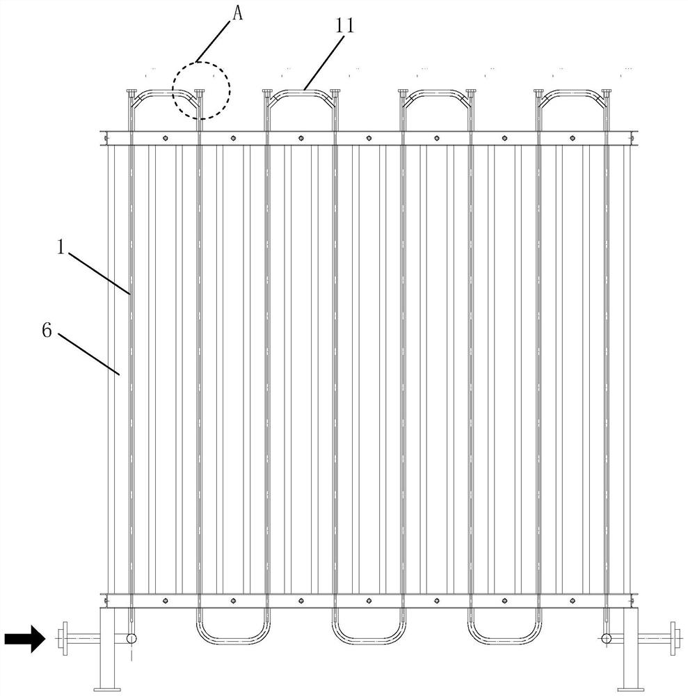
[0032] Such as Figure 3 to Figure 5As shown in , the high-efficiency all-weather air-temperature vaporizer described in Embodiment 2 of the present invention has basically the same structure as Embodiment 1, including a finned tube 1 and a multiplier 2. The inside of the finned tube 1 has a A multiplier 2 arranged in the central direction, the multiplier 2 makes the inside of the finned tube 1 form a spiral guide channel. The only difference is that the inside of the finned tube 1 has an electric heating rod 3 arranged along the axial direction, the electric heating rod 3 is installed in the multiplier 2, and the inner edge of the multiplier 2 The side is in direct contact with the outer surface of the electric heating rod 3; the specific structure can be: the booster 2 and the electric heating rod 3 can be an integrated structure, and one end of the electric heating rod 3 has a sealing head 4, integrated The multiplier 2 and the electric heating rod 3 of the structure are l...
PUM
 Abstract
Description
Claims
Application Information
 - R&D Engineer
- R&D Manager
- IP Professional
- Industry Leading Data Capabilities
- Powerful AI technology
- Patent DNA Extraction
Browse by: Latest US Patents, China's latest patents, Technical Efficacy Thesaurus, Application Domain, Technology Topic, Popular Technical Reports.
© 2024 PatSnap. All rights reserved.Legal|Privacy policy|Modern Slavery Act Transparency Statement|Sitemap|About US| Contact US: help@patsnap.com


