
Dental implant and dental implant manufacturing method

A technology for dental implants and implants, which is applied in the fields of dental implants, dentistry, and dental repairs, etc., can solve the problems of large stress shielding and poor osseointegration of dental implants, and achieve small stress shielding and solve osseointegration performance Poor, the effect of improving osseointegration performance

Pending Publication Date: 2020-12-08
SHANGHAI INST OF TECH
View PDF0 Cites 1 Cited by
  • Summary
  • Abstract
  • Description
  • Claims
  • Application Information

AI Technical Summary

Problems solved by technology

[0006] The technical problem to be solved by the present invention is to provide a dental implant and a manufacturing method of the dental implant to solve the problems of poor osseointegration and large stress shielding of the existing dental implants

Method used


Image

  • Dental implant and dental implant manufacturing method
  • Dental implant and dental implant manufacturing method
  • Dental implant and dental implant manufacturing method

Examples


Embodiment 1

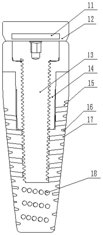
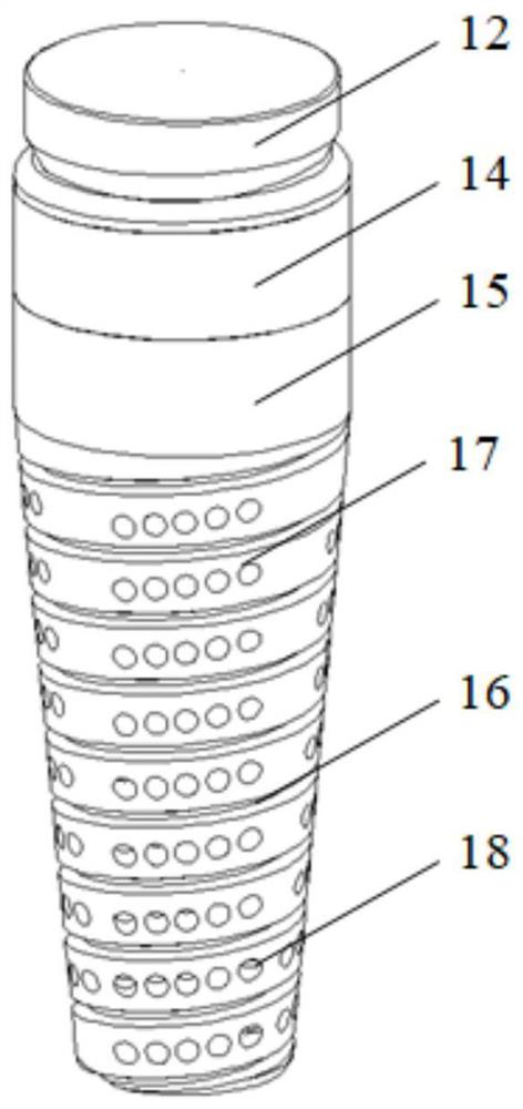
[0039] see Figure 1 to Figure 4 , In one embodiment, a dental implant includes an implant 15 , a fixing screw 13 , a fixing abutment 14 , and a treatment cap 12 .

[0040] Wherein, the implant body 15 includes an end portion and a cone portion. The upper end of the cone part is connected with the lower end of the end part. The diameter of the lower base of the cone is smaller than the diameter of the upper base. The outer surface of the cone is provided with an external thread 16 . The external thread 16 is respectively provided with a first pore area 17 and a second pore area 18 from bottom to top. Several first pores are opened in the first pore area 17 , and second pores are opened in the second pore area 18 . Wherein, the first hole is a through hole, and the second hole is a blind hole.

[0041] An accommodating space is opened at the upper end of the implant body 15 formed by the cooperation of the end portion and the taper portion. The lower end of the fixed base...

Embodiment 2

[0054] A method for manufacturing a dental implant, used to manufacture the dental implant in the first embodiment, the specific steps are as follows:

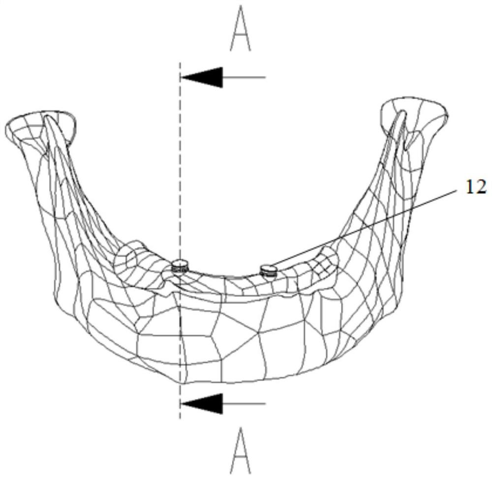
[0055] S1: Use the DICOM modeling method, use CT technology to photograph the edentulous mandible, obtain the corresponding CT data, and use the medical image software Minics, reverse engineering software Geomagic and 3D design software SolidWorks to establish a model including the edentulous mandible, mucosa and the first 3D finite element model of the denture. The purpose of constructing this model is to simulate the actual application effect of dental implants in real implant situations;

[0056] S2: Through the drawing of the dental implant, each part of the three-dimensional model of the dental implant is established in SolidWorks, and assembled to form a second three-dimensional finite element model of the dental implant.

[0057] S201: Carry out detail processing on the implant 15, draw a helix along the slope from the...


PUM

PropertyMeasurementUnit
diameteraaaaaaaaaa
diameteraaaaaaaaaa
pore sizeaaaaaaaaaa

Abstract

The invention discloses a dental implant and a dental implant manufacturing method. The dental implant comprises an implant body, a fixing screw, a fixing abutment and a treatment cap. The implant body comprises an end part and a conical part. The implant body is provided with the end part and the conical part which are connected in an up-down mode, an external thread is arranged on the conical part, and the external thread is divided into a first pore area with a first pore and a second pore area with a second pore in an up-down mode, so that when the implant body is combined with the bone tissue, the first pore area set as a through hole is conveniently combined with the bone tissue of the dense bone, and the second pore area set as a blind hole is conveniently combined with the bone tissue of the cancellous bone; and therefore, the elasticity modulus of the implant body is optimized, the osseointegration performance of the dental implant is improved, the strength is proper, the stress shielding is smaller, the biomechanical property is good, and the problems that an existing dental implant is poor in osseointegration performance and relatively large in stress shielding are solved.

Description

technical field [0001] The invention belongs to the field of oral implant technology, in particular to a dental implant and a method for manufacturing the dental implant. Background technique [0002] Due to factors such as poor fixation of the traditional treatment methods of complete dentures, they have been gradually replaced by implant-retained / supported overdentures. Seeking ideal osseointegration is a development direction of dental implantology today. [0003] At present, pure titanium and its alloys are clinically dominant implant materials. However, the chemical composition of titanium is completely different from natural bone tissue. The elastic modulus of pure titanium is 102-108GPa, that of titanium alloy (Ti6Al4V) is 110-120GPa, and that of human bone tissue is only 1.37-15GPa. [0004] The ratio of elastic modulus of pure titanium and its alloy materials to bone tissue is as high as ten to several tens of times, which will produce stress shielding after impla...

Claims


Application Information

Patent Timeline
Patent Type & Authority Applications(China)
IPC IPC(8): A61C8/00G06F30/23G06T17/00B22F3/105B33Y10/00
CPCA61C8/0037B33Y10/00G06T17/00G06F30/23
Inventor 张建国刘隽陈晨黄道宇
Owner SHANGHAI INST OF TECH
Learn More