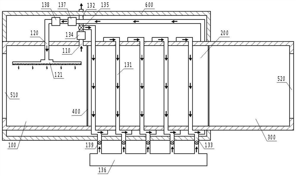
Sintering and paraffin removal furnace for ceramic production

A technology of wax removal furnace and ceramics, which is applied in the field of ceramic firing kilns, which can solve the problem that the waste heat of ceramic sintering cannot be utilized in the wax removal process, and achieve the effects of stable and controllable heating process, improved utilization rate, and improved combustion rate

Active Publication Date: 2020-11-20
溆浦易锋精细瓷业有限责任公司
View PDF6 Cites 0 Cited by
  • Summary
  • Abstract
  • Description
  • Claims
  • Application Information

AI Technical Summary

Problems solved by technology

[0004] The main purpose of the present invention is to provide a sintering wax removal furnace for ceramic production, aiming to solve the problem that the waste heat of ceramic sintering cannot be utilized by the wax removal process

Method used


Image

  • Sintering and paraffin removal furnace for ceramic production

Examples


Embodiment Construction

[0023] The following will clearly and completely describe the technical solutions in the embodiments of the present invention with reference to the accompanying drawings in the embodiments of the present invention. Obviously, the described embodiments are only part of the embodiments of the present invention, not all of them. Based on the embodiments of the present invention, all other embodiments obtained by persons of ordinary skill in the art without creative efforts fall within the protection scope of the present invention.

[0024] It should be noted that all directional indications (such as up, down, left, right, front, back...) in the embodiments of the present invention are only used to explain the relationship between the components in a certain posture (as shown in the accompanying drawings). Relative positional relationship, movement conditions, etc., if the specific posture changes, the directional indication will also change accordingly.

[0025] In addition, in t...


PUM


Abstract

The invention discloses a sintering and paraffin removal furnace for ceramic production. The sintering and paraffin removal furnace comprises a furnace body. The furnace body comprises a paraffin removal segment, a sintering segment and a cooling segment. A gas outlet and a gas inlet are formed on the paraffin removal segment and are in communication through a flow guide pipe. The flow guide pipecomprises a main pipe, and the main pipe surrounds the outer side of the sintering segment. In the technical scheme, gas in the paraffin removal segment is heated by arranging the main pipe surrounding the outer side of the sintering segment so as to achieve the temperature increase effect, waste heat of the sintering segment can be fully utilized, energy consumption can be reduced, and energy saving can be achieved. Meanwhile, due to the fact that ceramic production quality is influenced by black smoke generated by insufficient combustion of paraffin gas, gas mixed with black smoke can be immediately pumped out by arranging a first gas pump, temperature increase is achieved through the surrounding structure of the main pipe, oxygen is supplied into the main pipe through a second gas pumpto improve the combustion rate of paraffin gas, and therefore the black smoke content is reduced.

Description

technical field [0001] The invention relates to the technical field of ceramic firing kilns, in particular to a sintering wax removal furnace for ceramic production. Background technique [0002] Ceramic molding includes various processes such as injection molding, dry powder molding, and hot die-casting molding. Among them, hot die-casting molding can form products with complex shapes, and has the advantages of simple process and low mold cost, so it is widely used. When using the hot die casting molding process, the ceramic mud must be dewaxed before sintering. [0003] The existing wax removal process usually uses combustion or electric heating to directly heat the kiln, so that the ceramic mud body in it is heated to heat up, thereby realizing wax removal. However, on the one hand, the heating rate of this combustion or electric heating method is too fast and it is difficult to be accurately controlled, so that the heating curve of the ceramic mud body cannot meet the t...

Claims


Application Information

Patent Timeline
Patent Type & Authority Applications(China)
IPC IPC(8): F27B17/00F27D19/00F27D17/00F27D1/00
CPCF27B17/0041F27D19/00F27D17/004F27D1/00F27D2019/0003F27D2019/0078
Inventor 易辉
Owner 溆浦易锋精细瓷业有限责任公司
Why Eureka
Try Eureka