Residue recycling device for plastic product polishing and work method thereof

A technology for plastic products and recycling devices, which is applied in the direction of grinding/polishing safety devices, manufacturing tools, grinding workpiece supports, etc., which can solve the problems of reduced functionality, plastic residue fragmentation, and easy blockage, so as to improve its own functions sexual effect

Active Publication Date: 2020-11-13
泗县东方塑料有限责任公司
View PDF16 Cites 0 Cited by
  • Summary
  • Abstract
  • Description
  • Claims
  • Application Information

AI Technical Summary

Problems solved by technology

[0005] In order to overcome the dust-absorbing structural design of the traditional plastic product grinding residue recovery device, it can only recover the residue generated during plastic product grinding, which reduces the functionality of the plastic product grinding residue recovery device, making the residue recovery device It is impossible to compress the recovered plastic residues, which is not conducive to the user’s collection of residues; at the same time, the traditional residue recovery device does not have an auxiliary discharge structure, which increases the difficulty of taking out the compressed plastic residues, making the compressed plastic residues Fragmentation is prone to occur during the removal process; secondly, the traditional plastic product grinding residue recovery device does not have a rotary dredging structure, which makes the plastic product grinding residue recovery device prone to blockage during long-term use. Product grinding residue recovery device

Method used


Image

  • Residue recycling device for plastic product polishing and work method thereof
  • Residue recycling device for plastic product polishing and work method thereof
  • Residue recycling device for plastic product polishing and work method thereof

Examples


Embodiment Construction

[0031] The technical solutions in the embodiments of the present invention will be clearly and completely described below in conjunction with the embodiments of the present invention. Apparently, the described embodiments are only some of the embodiments of the present invention, not all of them. Based on the embodiments of the present invention, all other embodiments obtained by persons of ordinary skill in the art without creative efforts fall within the protection scope of the present invention.

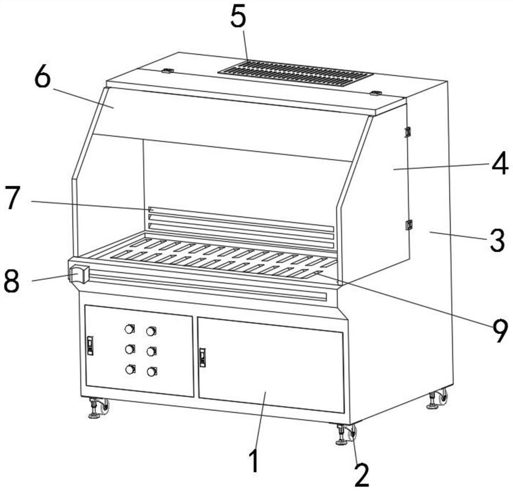
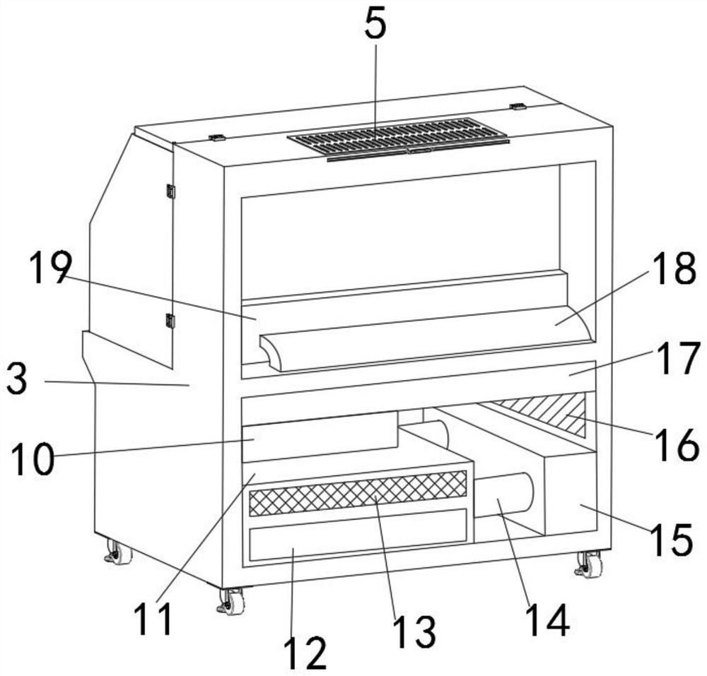
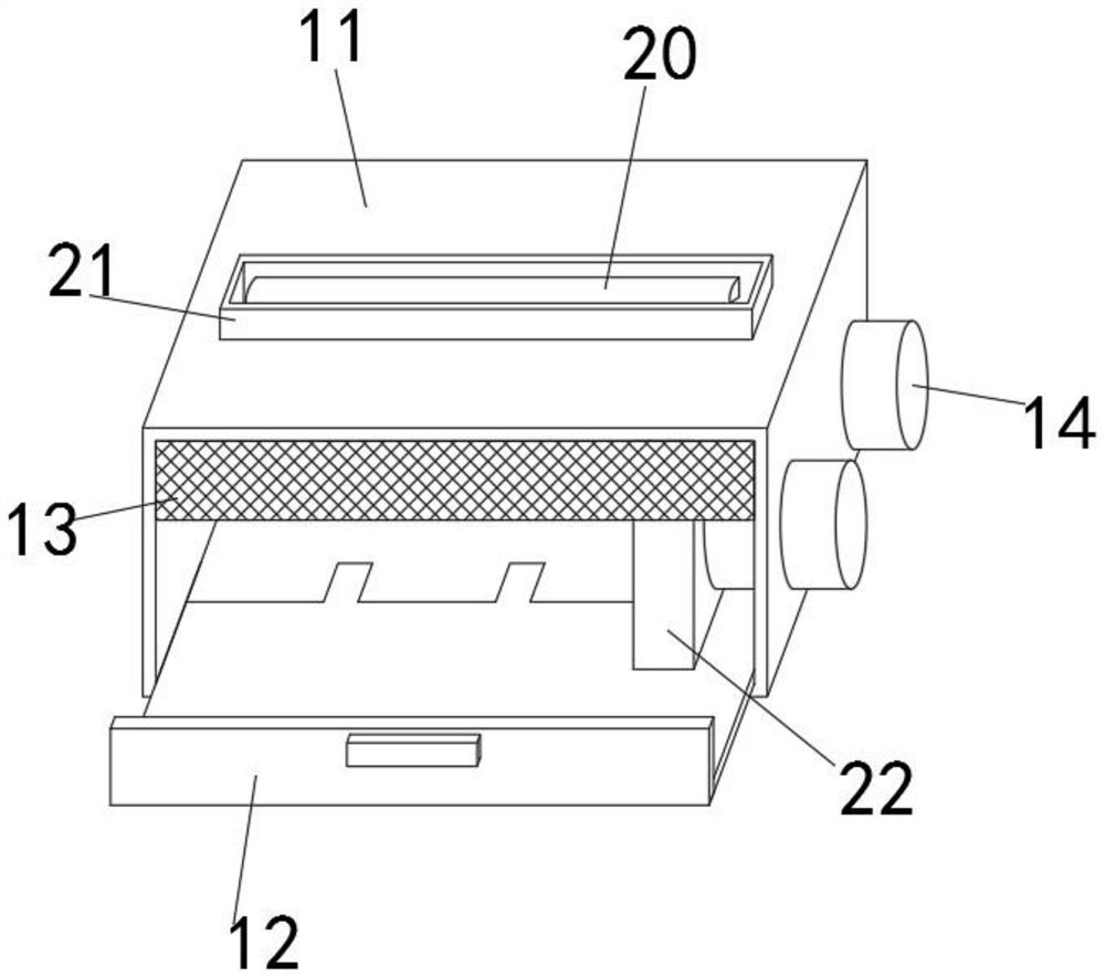
[0032] Such as Figure 1-5 As shown, a plastic product grinding residue recovery device includes a box shell 3, a storage box 11 and a drawer holder 12, the storage box 11 is fixedly installed inside the box shell 3, and the inside of the box shell 3 is close to the storage The upper end of the box 11 is fixedly equipped with a vacuum cleaner 17, and the inside of the storage box 11 is movably equipped with a pressing push block 22, and the inside of the storage box 11 is movably ...


PUM


Abstract

The invention discloses a residue recycling device for plastic product polishing and a work method thereof. The residue recycling device for plastic product polishing comprises a box shell, a storagebox and a push-and-pull clamp seat. The storage box is fixedly installed in the box shell. The inside of the box shell is fixedly provided with a dust collector close to the upper end of the storage box. The inside of the storage box is movably provided with a tightly pressing push block. The inside of the storage box is movably provided with the push-and-pull clamp seat and close to the lower endof the tightly pressing push block. The outer surface of one end of the push-and-pull clamp seat is movably provided with a rotating clamp seat. A rotating shaft is connected between the push-and-pull clamp seat and the rotating clamp seat in a sleeved manner. The inside of one end of the rotating clamp seat is provided with two groups of butt joint grooves in parallel. According to the residue recycling device for plastic product polishing, the residue recycling device for plastic product polishing is provided with an auxiliary compressing structure, so that the occupied space by the plasticresidues during recycling is reduced; and the residue recycling device for plastic product polishing is also provided with an auxiliary discharging structure, so that material fetching operation is more convenient and rapider, and the residue recycling device for plastic product polishing is convenient to use.

Description

technical field [0001] The invention belongs to the technical field of recycling devices, and more specifically relates to a recycling device for plastic product grinding residues. Background technique [0002] The residue recovery device for grinding plastic products is a residue recovery device for recycling the residue generated during the grinding of plastic products during the grinding process of plastic products. The residue recovery device for plastic product grinding can be used to quickly collect Plastic residues are convenient for users to reuse them. [0003] The comparison document CN108852152A discloses a powder metallurgy processing residue recovery device, which includes a pressing block, a movable rod, a limit snap ring, a pressing plate, a dust suction shell, a dust suction pipe, a fan, a blanking plate, and a slag inlet. The top of the movable rod and the annular side of the movable rod are equipped with a limited snap ring, the movable rod is set in the m...

Claims


Application Information

Patent Timeline
IPC IPC(8): B24B19/22B24B41/02B24B41/06B24B55/06
CPCB24B19/22B24B41/02B24B41/06B24B55/06
Inventor 姜日体姜荣榜
Owner 泗县东方塑料有限责任公司
Why Eureka
Try Eureka