Industrial flow meter for multi-fluid micro flow detection

A flow detection, multi-fluid technology, applied in the field of flow meters, can solve the problems of no auxiliary fixed structure, increased operation steps, no telescopic adjustment structure, etc., to achieve the effect of convenient installation and maintenance operation, reduced resistance, and firm docking

Active Publication Date: 2020-04-07
JIANGSU MICRO WAVE ELECTRONICS TECH
View PDF7 Cites 0 Cited by
  • Summary
  • Abstract
  • Description
  • Claims
  • Application Information

AI Technical Summary

Problems solved by technology

[0004] The existing industrial flowmeters for multi-fluid micro-flow detection have certain disadvantages in the process of use. The traditional industrial flowmeters for multi-fluid micro-flow detection do not have a fast docking structure. During the installation and maintenance of the industrial flowmeter for fluid micro-flow detection, the operation steps for the user to dock the fixed industrial flowmeter are increased; at the same time, the traditional industrial flowmeter for multi-fluid micro-flow detection does not have a telescopic adjustment structure, making it impossible The maximum capacity can be adjusted arbitrarily according to the volume of the fluid, thereby reducing the flexibility of the industrial flowmeter for multi-fluid micro-flow detection. At the same time, the traditional industrial flowmeter for multi-fluid micro-flow detection does not have an auxiliary fixed structure, making it impossible to The industrial flowmeter after the telescopic adjustment is fixed, which brings certain adverse effects to the user

Method used


Image

  • Industrial flow meter for multi-fluid micro flow detection
  • Industrial flow meter for multi-fluid micro flow detection
  • Industrial flow meter for multi-fluid micro flow detection

Examples


Embodiment Construction

[0035] The technical solutions in the embodiments of the present invention will be clearly and completely described below in conjunction with the embodiments of the present invention. Apparently, the described embodiments are only some of the embodiments of the present invention, not all of them. Based on the embodiments of the present invention, all other embodiments obtained by persons of ordinary skill in the art without creative efforts fall within the protection scope of the present invention.

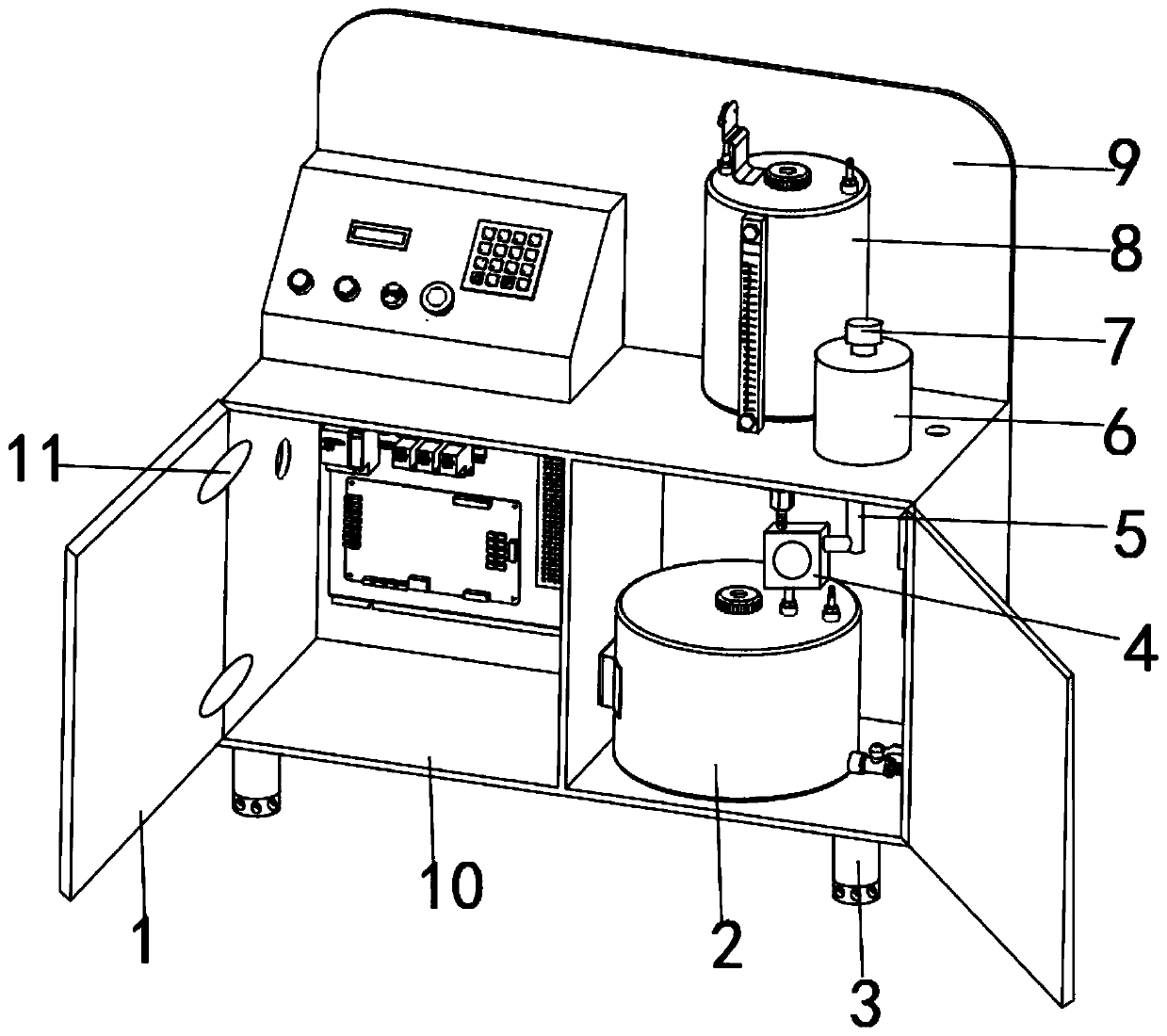
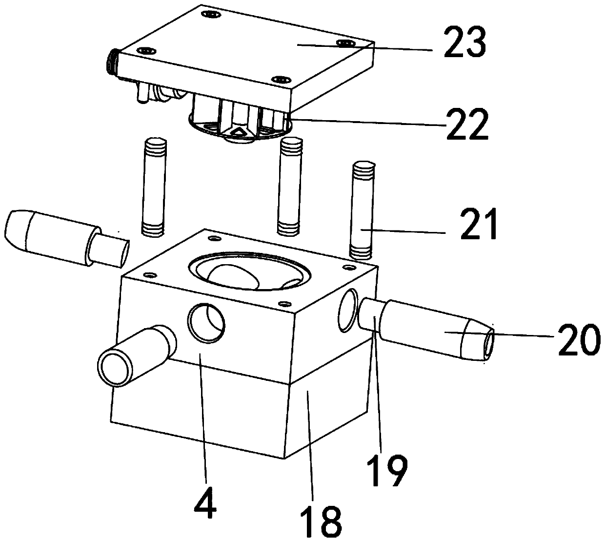
[0036] Such as Figure 1-6 As shown, an industrial flow meter for multi-fluid micro-flow detection includes a box casing 10 and a flow box 4. The flow box 4 is composed of a turbine blade 22, a meter 18 and a docking conduit 20. The turbine blade 22 is movable. Installed on the inner side of the upper part of the flow box 4, and the turbine rotor blade 22 and the flow box 4 are docked and fixed by the rotating shaft. The space is docked and fixed by supporting upright rods 21, an...


PUM


Abstract

The invention discloses an industrial flow instrument for multi-fluid micro-flow detection. The industrial flow instrument comprises a box body shell and a flow box, the flow box is composed of a turbine rotary vane, a meter and a butt joint guide pipe. The turbine rotary vane is movably mounted on the inner side of the upper part of the flow box; the turbine rotary vane and the flow box are butted and fixed through a rotating shaft; a sealing top cover is fixedly mounted on the outer surface of the upper end of the flow box; the flow box and the sealing top cover are butted and fixed througha supporting vertical rod; the meter is fixedly mounted on the outer surface of the lower end of the flow box; the butt joint guide pipe is fixedly connected to the middle of the outer surface of theside edge of the flow box in a sleeving mode. The butt joint guide pipe and the flow box are fixed in a butt joint mode through a fixing clamping pipe. The industrial flow instrument for multi-fluid micro-flow detection is provided with a rapid butt joint structure, the difficulty of installation and maintenance operation of the industrial flow instrument is reduced, meanwhile, the industrial flowinstrument is provided with a telescopic adjusting structure, and the application range of the industrial flow instrument is widened.

Description

technical field [0001] The invention belongs to the technical field of flow meters, and in particular relates to an industrial flow meter, in particular to an industrial flow meter for multi-fluid micro-flow detection. Background technique [0002] The industrial flowmeter for multi-fluid micro-flow detection is a kind of flow detection instrument that can detect the micro-flow of various fluids. The industrial flowmeter can detect the flow velocity and flow rate of fluids. [0003] A stratified flow pressure flowmeter disclosed in the comparative document CN201635718U includes rope caps connected in sequence; the main body of the instrument is sequentially provided with a throwing arm, an upper pressure probe, and a water nozzle docking part; a water inlet pipe connected to the throwing body, The first ultrasonic probe and the second ultrasonic probe are arranged in sequence; the lower end of the water inlet pipe is connected to the guide key part; the sensor seat is sealed...

Claims


Application Information

Patent Timeline
Patent Type & Authority Applications(China)
IPC IPC(8): G01F1/05G01F7/00G01P5/06
CPCG01F1/05G01F7/00G01P5/06
Inventor 刘建兵徐峰
Owner JIANGSU MICRO WAVE ELECTRONICS TECH
Why Eureka
Try Eureka