Handrail with limiting function for tractor and mounting method thereof

The utility model relates to a tractor and functional technology, which is applied to the handrail field of the tractor with a limit function, and can solve the problems of reducing the comfort of the tractor handrail, the single auxiliary support function of the tractor handrail, and the tractor handrail having no auxiliary buffer structure, etc., so as to achieve improved functionality and convenience. effect used

Active Publication Date: 2020-09-18
ANHUI SIZHOU TRACTOR MFG CO LTD
View PDF10 Cites 0 Cited by
  • Summary
  • Abstract
  • Description
  • Claims
  • Application Information

AI Technical Summary

Problems solved by technology

[0004] The existing tractor handrails have certain disadvantages in the use process. The traditional tractor handrails only have a single auxiliary support function. They mainly perform steering operations on the walking tractor during driving. The auxiliary limit operation is performed during the tractor driving, which reduces the functionality of the tractor handrail itself; secondly, the traditional tractor handrail does not have an angle adjustment structure, so that the traditional tractor handrail cannot be adjusted at any angle according to the user's needs, thereby reducing the use of the tractor handrail. At the same time, the traditional tractor handrail does not have an auxiliary buffer structure, and the tractor will produce a certain vibration during driving. The vibration is transmitted to the handle through the tractor handrail. The user's hand reduces the comfort when operating the tractor armrest and brings certain adverse effects to the user

Method used


Image

  • Handrail with limiting function for tractor and mounting method thereof
  • Handrail with limiting function for tractor and mounting method thereof
  • Handrail with limiting function for tractor and mounting method thereof

Examples


Embodiment Construction

[0033] The technical solutions in the embodiments of the present invention will be clearly and completely described below in conjunction with the embodiments of the present invention. Apparently, the described embodiments are only some of the embodiments of the present invention, not all of them. Based on the embodiments of the present invention, all other embodiments obtained by persons of ordinary skill in the art without creative efforts fall within the protection scope of the present invention.

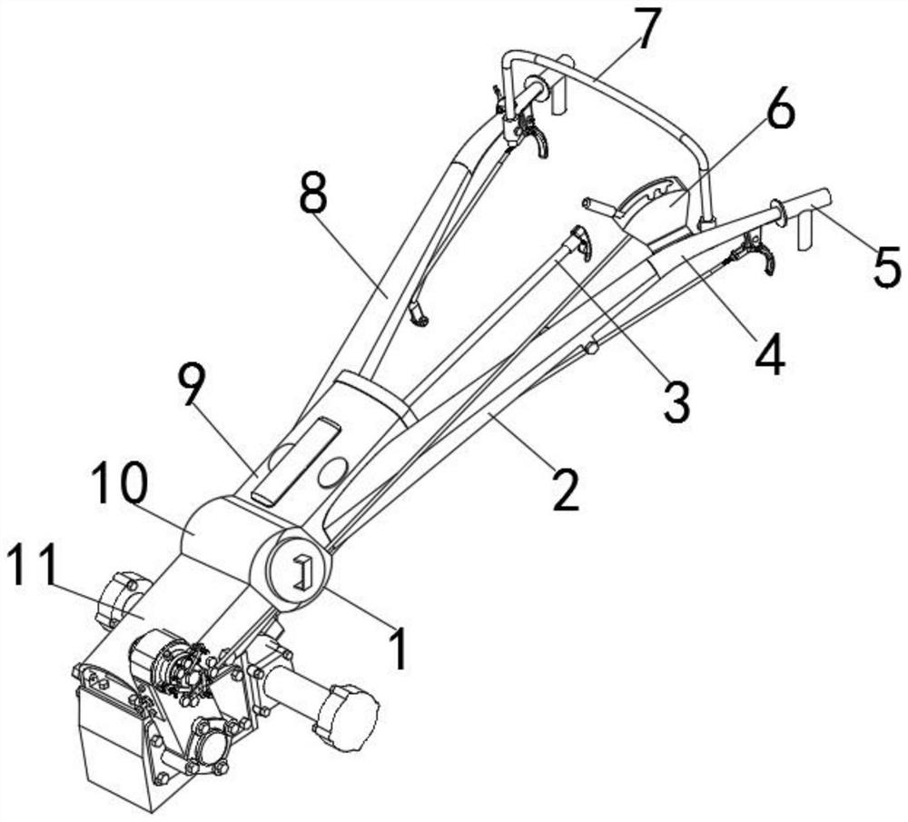
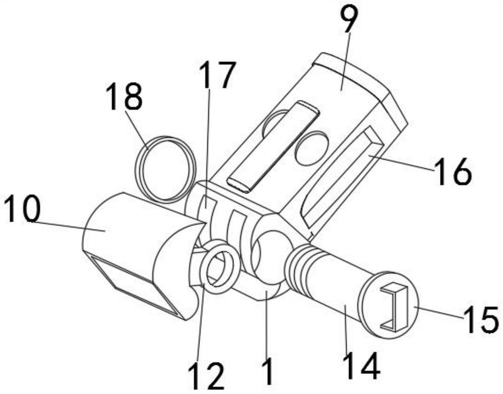
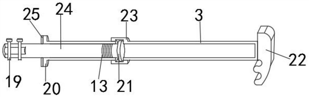
[0034] Such as Figure 1-6 As shown, a handrail with a position-limiting function for a tractor includes a first socket 9, a second socket 11, a first rail 2 and a second rail 8, and the first rail 2 is fixedly sleeved on the second One side outer surface of the first socket 9, the second support rod 8 is fixedly sleeved on the other side outer surface of the first socket 9, the second socket 11 is arranged at one end of the first socket 9, the first socket The outer surface of o...


PUM


Abstract

The invention discloses a handrail with a limiting function for a tractor. The handrail comprises a first connecting base, a second connecting base, a first handrail body and a second handrail body. The outer surface of one side of the first connecting base is fixedly sleeved with the first handrail. The second handrail is fixedly connected to the outer surface of the other side of the first connecting seat in a sleeving manner; the second connecting seat is arranged at one end of the first connecting seat; a first clamping seat is fixedly mounted on the outer surface of one end of the first connecting seat; a second clamping base is fixedly installed on the outer surface of one end of the second connecting base, the first connecting base and the second connecting base are fixed in a buttjoint mode through a first clamping base and a second clamping base, two sets of rotating grooves are formed in the inner side of the first clamping base, and two sets of rotating clamping rings are fixedly installed on the outer surface of the side edge of the second clamping base. According to the invention, the tractor handrail is provided with the limiting and locking structure, so that the functionality of the tractor handrail is improved, meanwhile, the tractor handrail is provided with the rotary angle adjusting structure, and the operation flexibility of the tractor handrail is improved.

Description

technical field [0001] The invention belongs to the technical field of tractor equipment, in particular to a handrail with a position-limiting function for a tractor. Background technique [0002] A tractor is a self-propelled power machine used to pull and drive work machinery to complete various mobile operations. It can also be used as a fixed work power. And traction and other systems or devices, the engine power is transmitted from the transmission system to the driving wheels to make the tractor run. In real life, rubber belts are commonly used as the power transmission medium. [0003] A telescoping tractor handle disclosed in comparative document CN210083320U includes a headstock, a box body is fixedly connected to one side outer wall of the headstock, and a cavity is opened inside the box body, and the inner wall of the side close to the headstock is symmetrical. There is a first groove, the inner walls of the two first grooves are fixedly connected with mounting s...

Claims


Application Information

Patent Timeline
IPC IPC(8): B62D1/12B62D49/00
CPCB62D1/12B62D49/00
Inventor 朱一峰朱如龙徐锡冲张守民
Owner ANHUI SIZHOU TRACTOR MFG CO LTD
Why Eureka
Try Eureka