Due to the importance of the role of the motor rotor bearing, generally in the production of industrial motors, a circle of lubricating oil will be smeared on the outside of the bearing to play the role of lubricating the motor bearing, thereby prolonging the service life of the motor. However, due to the location of some motors If the environment or its own
operating temperature is too high, cooling air teeth are usually added to the motor rotor. Generally, the height of the cooling air teeth is relatively high, which may block some or even all of the bearings. It is relatively laborious, and the traditional smearing process can only be done manually;
Chinese patent 201420365417.3 discloses an unpowered automatic oiling device for motor rotor ball bearings, including an oiling inclined frame, a groove set on the oiling inclined frame and a groove in the concave Oiled rails on both sides of the groove, linoleum is set in the oiled rail, and a stop plate is installed at the end of the oiled inclined frame. The oiled rail is set obliquely. When oiling the ball bearings, the ball bearings can automatically due to gravity. Roll from the upper end of the oiling track to the lower end, without external force, realize automatic oiling, solve the trouble of manual oiling with an oil
brush for traditional oiling, the inclination of the oiling track is consistent with the inclination of the oiling inclined frame, oiling The angle between the inclined frame and the horizontal plane is between 7°-25°, the cross section of the oil track is "U" shaped, and the shape of the linoleum coincides with the inner wall of the oil-coated track and evenly covers the inner wall of the oil-coated track ;
Chinese patent 201410834168.2 discloses an oiling
machine, including a frame, an oiling device and a rotor arrangement device are arranged on the frame, a chute guide rail is provided between the oiling device and the rotor arrangement device, and the oiling device includes a
numerical control oiling The gear and the synchronous belt controlled by the deceleration motor, the end surface of the chute guide rail is provided with a rotor preparation tank connected with it, the rotor preparation tank is provided with a bracket for fixing the
timing belt, the rotor preparation tank and the
numerical control oiler are connected through the oil
pipe, The CNC oiler is used to ensure that the oil is continuously input into the rotor preparation tank. After the rotor enters the rotor preparation tank, the CNC oiler starts to operate to realize automatic oil injection. A
timing belt controlled by a geared motor is set at the bottom of the rotor preparation tank to roll the rotor surface. Friction makes the oil contact with the rotor evenly and fully, realizes the
automation of rotor oiling, improves production efficiency, and reduces labor costs;
Chinese patent 201620640588.1 discloses a synchronous oiling device for motor rotor bearing positions, including a frame and a frame It is equipped with a transmission motor, a drive
assembly connected to the shaft of the transmission motor, and two sets of tension oiling assemblies connected to the drive
assembly. The drive
assembly includes the main
drive wheel on the shaft of the transmission motor and the sub The driving wheel, the driving belt is arranged between the main driving wheel and the auxiliary driving wheel, the tension oiling assembly includes the driven synchronous wheel connected with the output end of the driving assembly and the main oiling wheel arranged on the frame, the driven synchronous wheel and the main There is an oiling belt between the oiling wheels, and the oiling belt corresponds to the position of the rotor bearing of the motor. There is a tensioning oiling wheel on the frame. On the same plane and arranged in a triangle, the driven synchronous wheel, the main oiler and the tension oiler are connected by an oiling belt, and the driven synchronous wheel and Auxiliary drive wheels are set coaxially on the frame, and the frame is equipped with driven rollers, which are pressed against the back of the oiled belt, and the frame is equipped with an oil scraper that can move back and forth along the direction of the oiled belt. , the oil scraping plate is pressed against the oiling belt; Chinese patent 201621053801.5 discloses a
fully automatic finished bearing oiling equipment, including a frame, which is provided with a first oiling channel, a second oiling channel, connected to The middle guide rail between the first oiling channel and the second oiling channel for automatic transfer of bearings, the incoming material
conveyor belt connected to the end of the first oiling channel away from the middle guide rail, connected to the end of the second oiling channel away from the middle guide rail The
discharge guide rail, the front oiling assembly, the back oiling assembly, and the inner hole oiling assembly distributed along the length direction of the first oiling channel, and the frame is also equipped with a drive for driving the front oiling assembly, the reverse oiling assembly and the inner hole. The first drive assembly for the up and down movement of the hole oiling assembly. The first oiling channel is provided with a turning assembly between the front oiling assembly and the reverse oiling assembly. The first oiling channel is also equipped with The bearing on the belt moves along the first oiling channel and pushes into the first push assembly of the middle guide rail, and the second oiling channel is equipped with a bearing outer ring oiling device and pushes the bearing to move along the second oiling channel and pushes it in and out. The second push assembly of the material guide rail; Chinese patent 201620535893.4 discloses an oiling device for a motor rotor, including an oil inlet
pipe, an iron core
oil supply pump, a bearing
gear oil supply pump, an oil pipe, an oil
brush on the bearing gear, an iron core drip
nozzle, The
oil tanker, the tanker driving motor, the tanker
transmission belt and the tanker position adjustment device, wherein the oil inlet pipe is connected to the iron core
oil supply pump and the bearing
gear oil supply pump, and the iron core
oil supply pump and the bearing
gear oil supply pump supply oil to the oil pipe according to the working conditions; The oil pipe described above includes oil pipe one, oil pipe two and oil pipe three; the oil
brush on the bearing gear includes the oil brush one on the bearing gear and the oil brush two on the bearing gear; the oil pipe one connects the bearing gear oil supply pump and the oil brush on the bearing gear The
tail end of one, oil pipe two connect the oil supply pump of the bearing gear and the
tail end of the oil brush two on the bearing gear, the oil brush one on the bearing gear and the oil brush two on the bearing gear contact the two ends of the motor rotor, and feed the motor rotor Oil; the oil pipe three connects the iron core oil supply pump and the iron core oil drip
nozzle, the iron core oil drip
nozzle is located above the
oil tanker to supply oil to the
oil tanker; the oil tanker is located behind the motor rotor, the oil tanker
drive motor and the oil tanker are connected through the oil tanker
transmission belt to provide power for the oil tanker , to drive the oil tanker to rotate and oil the iron core; the oil tanker position adjustment device is set under the oil tanker to adjust the position of the oil tanker. When oiling, the oil tanker is moved to the iron core of the motor rotor. position; through the traditional process of manual oiling of motor rotor bearings, the production efficiency is low, and the uneven oiling will cause
motor noise. Although the above-mentioned patented product has improved the manual operation method, the structure of the patented product is complex And the function is single, which can realize the separate oiling process after the bearing is separated from the rotor, or can only meet the oiling requirements of the rotor bearings of ordinary motors without cooling wind teeth on the rotor body and the rotor bearings installed outside the cooling wind teeth, and the
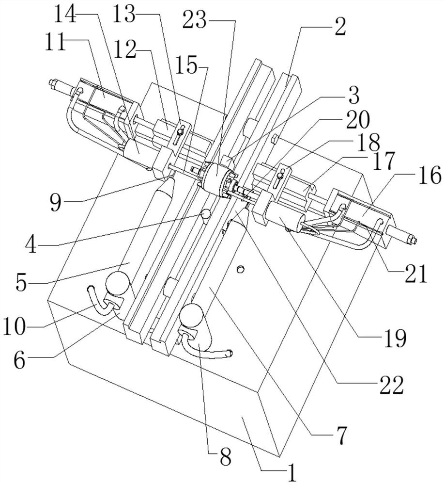
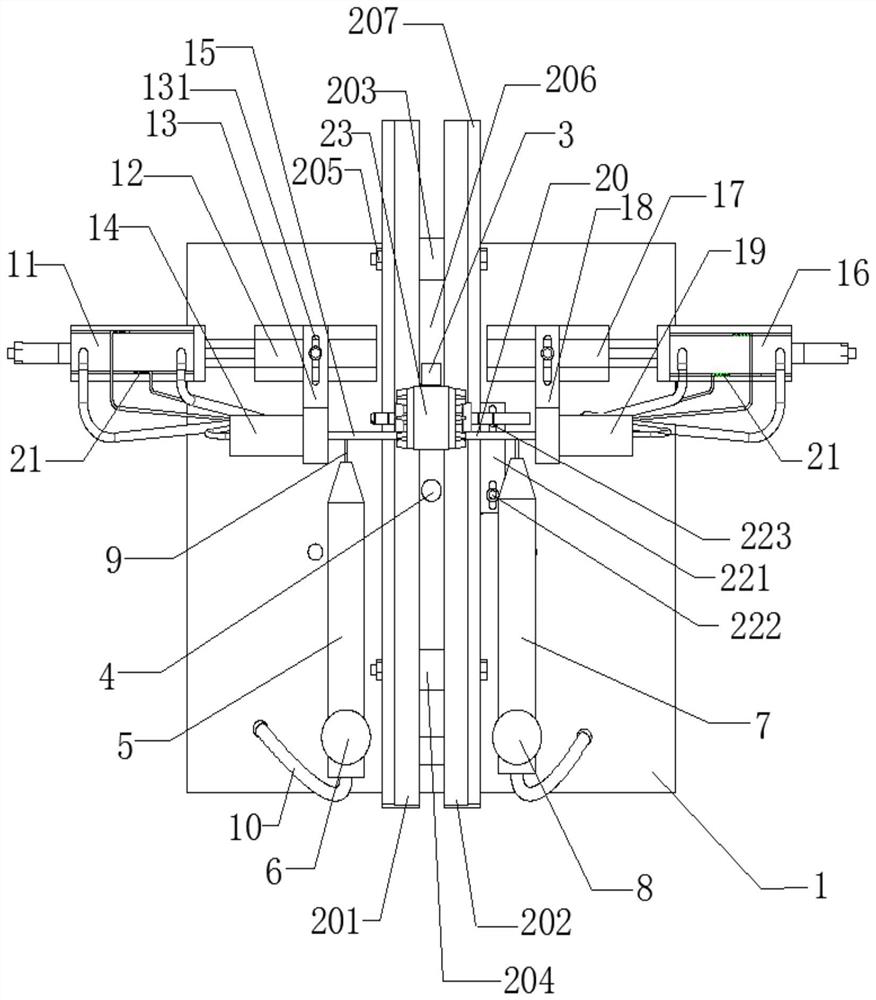
coating of the rotor bearings The oil is uneven, which affects the service life of the motor, and the use process is cumbersome , high cost; therefore, research and design a motor rotor bearing automatic oiling device with a scientific and reasonable structure, simple and convenient control, and a high degree of
automation, which can simultaneously meet the
coating requirements of the rotor bearing on the inside and outside of the cooling wind teeth on the rotor main body , can achieve rapid and even oiling of motor rotor bearings, improve the
coating quality of motor rotor bearings, prolong the service life of motors, improve production efficiency, and reduce the labor intensity of operators. It has good use value and promotion prospects

