Preparation method of lithium iron phosphate/carbon nanotube composite cathode material
A carbon nanotube composite and positive electrode material technology, which is applied in the direction of positive electrodes, battery electrodes, active material electrodes, etc., can solve problems such as difficult to remove, difficult to prepare composite materials, and poor dispersion of carbon nanotubes
- Summary
- Abstract
- Description
- Claims
- Application Information
AI Technical Summary
Problems solved by technology
Method used
Image

Examples
Embodiment 1
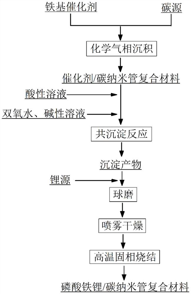
[0024] like figure 1 Shown, the embodiment of the present invention provides a kind of preparation method of lithium iron phosphate / carbon nanotube composite cathode material, comprises the following steps:
[0025] Step 1: take 50g median particle diameter and be the iron-based catalyst (iron content is 98wt%) of 0.82um, iron-based catalyst is put into the tubular electric resistance furnace, assemble experimental device and check the airtightness of device; Nitrogen is used to remove the air in the device, the nitrogen flow rate is 300 sccm, and the temperature of the tubular resistance furnace is raised to 750° C. at 15° C. / min. When the temperature in the furnace reached the set temperature, the nitrogen gas was turned off, and methane was fed in at the same time, and the gas flow rate was 100 sccm. After feeding ethylene for 25 minutes, stop feeding carbon source gas, start feeding nitrogen gas, keep warm for 30 min, cool down to room temperature naturally, and take out ...
Embodiment 2
[0031]Step 1: Weigh 50g of catalyst with a median particle size of 0.82um (98wt% iron content), put the catalyst into a tubular resistance furnace, assemble the experimental device and check the airtightness of the device. Nitrogen gas was introduced to remove the air in the device, the flow rate of nitrogen gas was 300 sccm, and the temperature of the tubular resistance furnace was raised to 750 °C at 15 °C / min. When the temperature in the furnace reached the set temperature, the nitrogen gas was turned off, and methane was fed in at the same time, and the gas flow rate was 100 sccm. After feeding ethylene for 25 minutes, stop feeding carbon source gas, start feeding nitrogen gas, keep warm for 30 min, cool down to room temperature naturally, take out the iron powder / carbon nanotube composite material; perform inductively coupled plasma spectroscopy (ICP-OES) on the material Test, it is found that the content of iron in the composite material is 88.78wt%;
[0032] Step 2: We...
Embodiment 3
[0037] Step 1: Weigh 50g of a catalyst with a median particle size of 2.54um (the iron content is 95wt%), put the catalyst into a tubular resistance furnace, assemble the experimental device and check the airtightness of the device. Argon gas was introduced to remove the air in the device, the flow rate of argon gas was 500 sccm, and the temperature of the tube resistance furnace was raised to 800 °C at 15 °C / min. When the temperature in the furnace reaches the set temperature, the argon gas is turned off, and acetylene is introduced at the same time, and the gas flow rate is 30 sccm. After feeding ethylene for 15 minutes, stop feeding carbon source gas, start feeding argon gas, keep warm for 20 min, cool down to room temperature naturally, and take out the iron powder / carbon nanotube composite material. The material was tested by inductively coupled plasma spectroscopy (ICP-OES), and the content of iron in the composite material was measured to be 84.37wt%;
[0038] Step 2: ...
PUM
| Property | Measurement | Unit |
|---|---|---|
| particle diameter | aaaaa | aaaaa |
Abstract
Description
Claims
Application Information
 - R&D
- Intellectual Property
- Life Sciences
- Materials
- Tech Scout
- Unparalleled Data Quality
- Higher Quality Content
- 60% Fewer Hallucinations
Browse by: Latest US Patents, China's latest patents, Technical Efficacy Thesaurus, Application Domain, Technology Topic, Popular Technical Reports.
© 2025 PatSnap. All rights reserved.Legal|Privacy policy|Modern Slavery Act Transparency Statement|Sitemap|About US| Contact US: help@patsnap.com