
Heat conduction adhesion silica gel

A thermally conductive silicone sheet, silicone technology, applied in the direction of adhesives, film/sheet adhesives, non-polymer adhesive additives, etc. It can improve the basic mechanical properties, high fluidity, and enhance the thickening effect.

Pending Publication Date: 2020-10-02
王朝鹏
View PDF10 Cites 0 Cited by
  • Summary
  • Abstract
  • Description
  • Claims
  • Application Information

AI Technical Summary

Problems solved by technology

[0004] In order to make up for the deficiencies in the prior art and solve the problem that the existing heat-conducting adhesive silica gel cannot have fluidity and ease of use at the same time, and the heat-conducting silica gel pad prepared by the existing heat-conducting adhesive silica gel has poor internal longitudinal heat dissipation capability, the present invention proposes A thermally conductive adhesive silicone

Method used


Image

  • Heat conduction adhesion silica gel
  • Heat conduction adhesion silica gel
  • Heat conduction adhesion silica gel

Examples


preparation example Construction

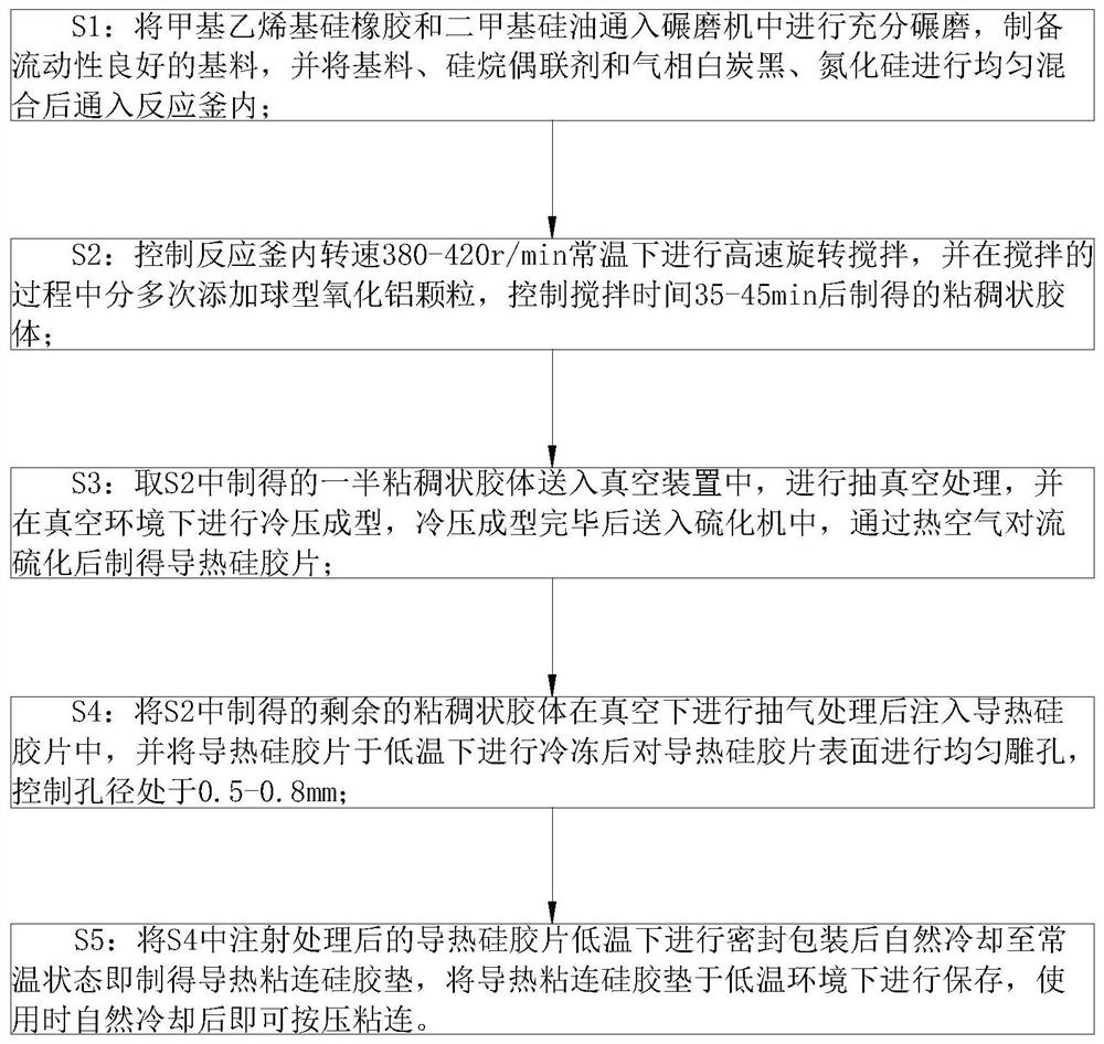
[0034] The preparation method of the thermally conductive adhesive silica gel comprises the following steps:

[0035] S1: Pass methyl vinyl silicone rubber and simethicone oil into a mill for full grinding to prepare a base material with good fluidity, and combine the base material, silane coupling agent and fumed silica, and nitriding The silicon is uniformly mixed and then passed into the reaction kettle; firstly, dimethyl silicone oil and methyl vinyl silicone rubber are used for grinding and mixing, and then other additive components are added, which can effectively speed up the preparation process;

[0036] S2: Control the rotation speed in the reaction kettle to 380-420r / min and carry out high-speed rotation and stirring at room temperature, and add spherical alumina particles several times during the stirring process, and control the stirring time for 35-45 minutes to obtain a viscous colloid; The spherical alumina particles are added several times, and the high-speed s...

Embodiment approach

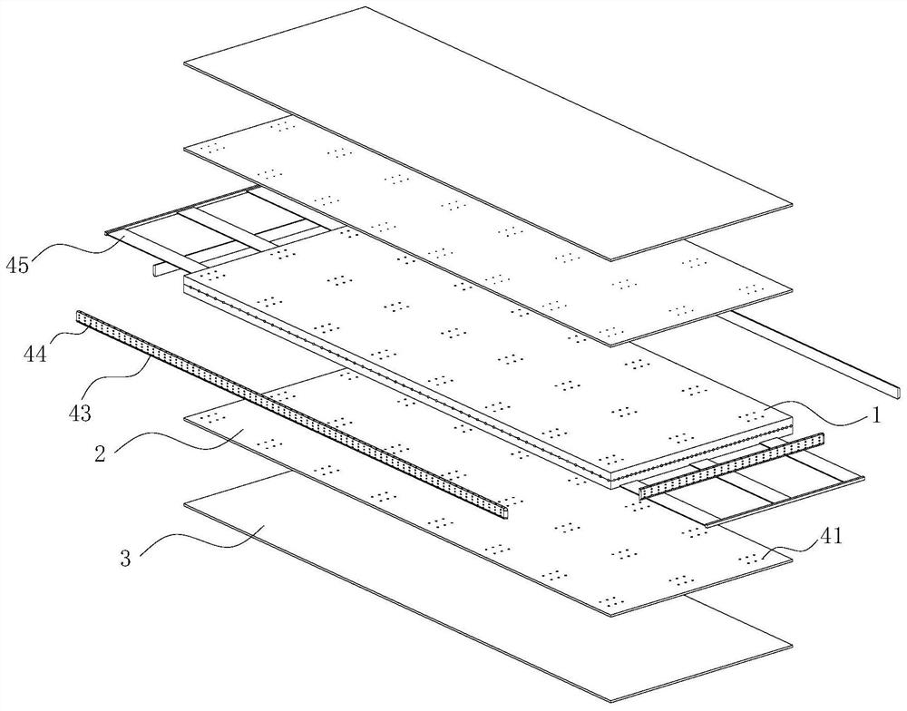
[0044] As an embodiment of the present invention, the heat dissipation holes 44 are designed in the shape of a truncated cone, and the area of ​​the side of the heat dissipation holes 44 close to the base layer 1 is smaller than the area of ​​the side of the heat dissipation holes 44 away from the base layer 1; conduction; when working, the heat is conducted to the heat dissipation bar 43 along the carbon fiber mesh, and through the contact between the heat dissipation bar 43 and the air, the heat dissipation effect is achieved. The setting of the heat dissipation hole 44 effectively increases the heat dissipation effect between the heat dissipation bar 43 and the air. The heat exchange area enhances the heat dissipation efficiency, and the truncated design of the heat dissipation holes 44 and the mutual conduction design of the heat dissipation holes 44 can effectively increase the air convection rate in the heat dissipation holes 44, thereby enhancing the heat dissipation rate...


PUM


Abstract

The invention belongs to the technical field of high polymer materials, and particularly relates to heat conduction adhesion silica gel which comprises two base layers, two adhesion layers and sealingpaper. The two base layers are adhered to each other; a carbon fiber net is fixedly connected to the mutual adhesion part of the base layers; first cavities which are evenly distributed are formed inthe base layers. The first cavities are filled with liquid glue. The two adhesion layers are fixedly connected to the opposite sides of the base layers respectively, and are provided with microporeswhich are uniformly distributed; the micropores extend into the first cavities. The opening area of the micropores in the first cavities is larger than the opening area of the micropores in the surface of the adhesion layers. Through the arrangement of heat dissipation strips and heat dissipation holes, heat is rapidly dissipated through air convection, meanwhile, the sealing performance of the first cavities is effectively improved through the arrangement of the sealing strips, and then a prepared heat conduction silica gel pad is more convenient to use.

Description

technical field [0001] The invention belongs to the technical field of polymer materials, in particular to a heat-conducting adhesive silica gel. Background technique [0002] In the prior art, thermally conductive adhesive silica gel is mostly divided into two types: solid and liquid. Solid thermally conductive adhesive silica gel is easy to use and easy to store, but it has the characteristics of weak adhesion on some special contact surfaces, such as contact surfaces with irregular surface depressions. , and then there are a lot of gaps on the adhesive surface, and the air itself is a poor conductor of heat. The existence of a large number of gaps hinders the heat in the transmission process, which in turn affects the thermal conductivity. They are in close contact with each other without gaps, but the liquid thermal silica gel is inconvenient to use and troublesome to operate. At the same time, the existing thermal silica gel pad itself has excellent lateral heat dissipa...

Claims


Application Information

Patent Timeline
Patent Type & Authority Applications(China)
IPC IPC(8): C09J183/07C09J183/04C09J11/04C09J7/30C09J7/20
CPCC09J183/04C09J11/04C09J7/30C09J7/20C08L2205/025C09J2400/10C09J2483/00C09J2400/28C08L83/04C08K13/06C08K9/06C08K7/26C08K7/18C08K3/34C08K7/06
Inventor 王朝鹏刘进取
Owner 王朝鹏
Learn More