
Vacuum cavity embedded aerogel type heat preservation shell for thermal battery and application of vacuum cavity embedded aerogel type heat preservation shell

A technology of vacuum insulation and aerogel, which is applied in the direction of electrical components, battery boxes/coats, battery pack components, etc., which can solve the development requirements of unfavorable thermal batteries to save space, unsatisfactory long-life thermal batteries, and unsatisfactory thermal insulation effects, etc. problem, to achieve the effect of improving thermal insulation effect, low solid thermal conductivity, and saving space

Active Publication Date: 2020-08-11
INST OF ELECTRONICS ENG CHINA ACAD OF ENG PHYSICS
View PDF16 Cites 2 Cited by
  • Summary
  • Abstract
  • Description
  • Claims
  • Application Information

AI Technical Summary

Problems solved by technology

Although nano-airgel materials can better meet the requirements of medium-life thermal batteries, they are not ideal for long-life thermal batteries, especially thermal batteries with a life of more than 1h.
[0005] For thermal battery insulation, in addition to choosing traditional porous materials, vacuum-airgel composite insulation shells have appeared, which have better insulation effects than airgel cartridges alone, but the cover area of ​​such insulation shells is usually It is designed for non-vacuum, and there is a phenomenon that a large amount of heat is lost from this area, and the overall thermal insulation effect is still not ideal; in addition, the current thermal insulation shell occupies a large volume because the airgel material and the vacuum cavity are separately set. It is also not conducive to the development requirements of thermal batteries in terms of space saving

Method used


Image

  • Vacuum cavity embedded aerogel type heat preservation shell for thermal battery and application of vacuum cavity embedded aerogel type heat preservation shell
  • Vacuum cavity embedded aerogel type heat preservation shell for thermal battery and application of vacuum cavity embedded aerogel type heat preservation shell
  • Vacuum cavity embedded aerogel type heat preservation shell for thermal battery and application of vacuum cavity embedded aerogel type heat preservation shell

Examples


Embodiment 1

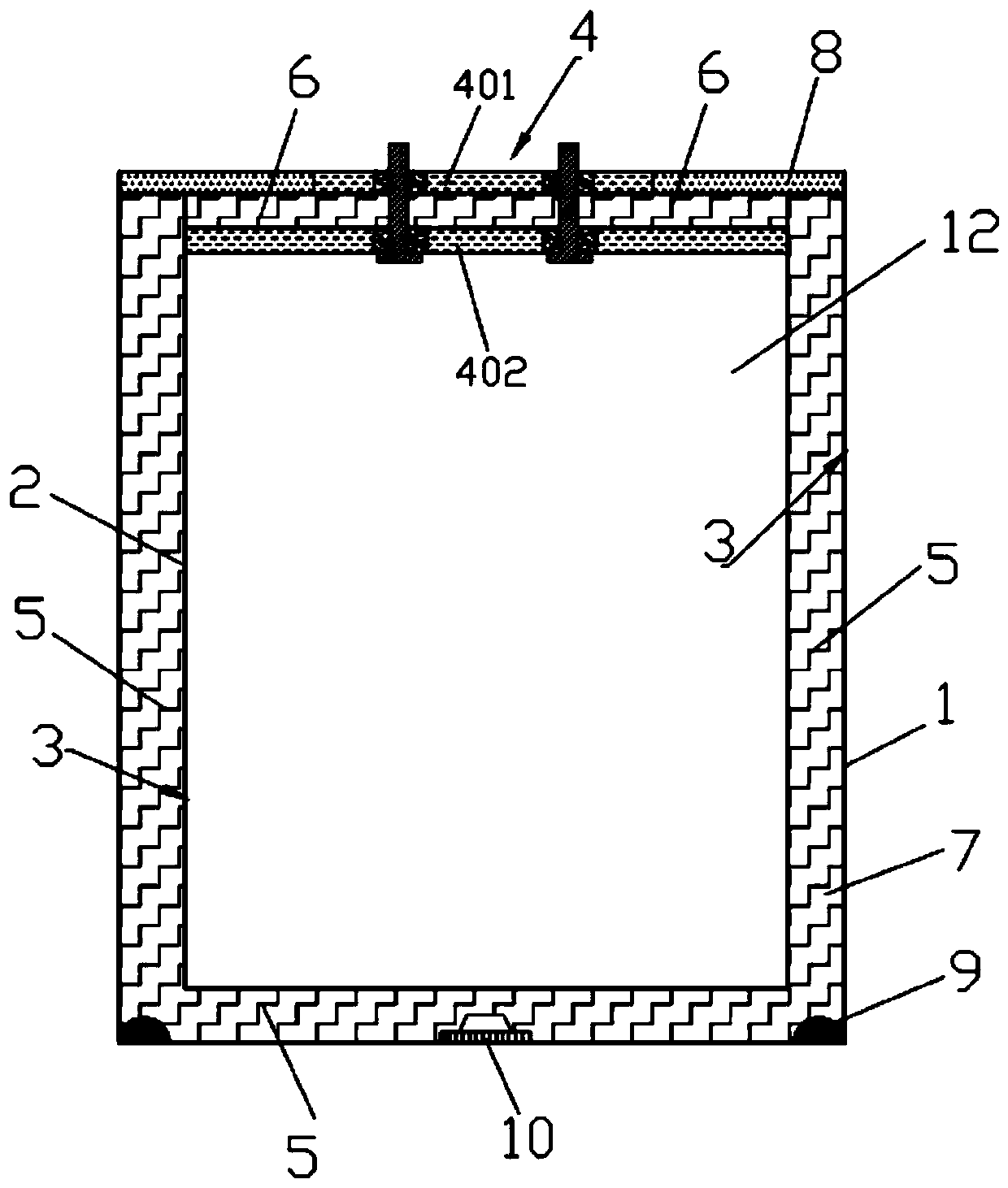
[0056] The battery case 1 and the battery inner case 2 are made of stainless steel 304, the reflective material aluminum is plated on the inner wall of the battery case 1 and the outer wall of the battery inner case 2, the thickness is 100 μm, and the getter material 9 barium is fixed inside the vacuum cavity aluminum alloy, and then the nano-silica airgel insulation tube 5 is packed into the battery casing 1. After the assembled battery cell stack 12 is put into the battery inner case 2, cover the battery cover 4, weld the lower cover 402 of the battery cover 4 with the battery inner case 2, and then install the airgel insulation block 6 between the upper and lower layers of the battery cover 4, then weld the upper cover 401 of the battery cover 4 to the inner edge of the outer ring 8 of the cover, and then weld the welded battery inner case 2 and battery cover 4 , nano-silica airgel insulation block 6, the combination of four parts of the outer ring 8 of the cover plate are ...

Embodiment 2

[0058] The battery case 1 and the battery inner case 2 are made of industrial pure titanium materials, and the reflective material aluminum is evaporated on the inner wall of the battery case 1 and the outer wall of the battery inner case 2, with a thickness of 50 μm, and the getter material is fixed inside the vacuum cavity 9 barium-titanium alloys, and then the nano-zirconia airgel insulation tube 5 is packed into the battery casing 1. After the assembled battery cell stack 12 is loaded into the battery inner shell 2, cover the battery cover plate 4, weld the lower cover plate 402 of the battery cover plate 4 with the battery inner shell 2, and then apply the nano zirconia airgel The insulation block 6 is put between the upper and lower layers of the battery cover plate 4, and then the upper layer cover plate 401 of the battery cover plate 4 is welded to the inner edge of the outer ring 8 of the cover plate, and then the welded battery inner shell 2, The battery cover plate ...

Embodiment 3

[0060] The battery case 1 and the battery inner case 2 are made of stainless steel 304 material, the reflective material aluminum is electroplated on the inner wall of the battery case 1 and the outer wall of the battery inner case 2, the thickness is 20 μm, and the getter material 9 zirconium is fixed inside the vacuum chamber aluminum alloy, and then the nano zirconia airgel insulation tube 5 is packed into the battery casing 1. After the assembled battery cell stack 12 is loaded into the battery inner shell 2, cover the battery cover plate 4, weld the lower cover plate 402 of the battery cover plate 4 with the battery inner shell 2, and then apply the nano-silica airgel The insulation block 6 is put between the upper and lower layers of the battery cover plate 4, and then the upper layer cover plate 401 of the battery cover plate 4 is welded to the inner edge of the outer ring 8 of the cover plate, and then the welded battery inner shell 2, The battery cover plate 4, the ai...


PUM

PropertyMeasurementUnit
thicknessaaaaaaaaaa
thicknessaaaaaaaaaa
thicknessaaaaaaaaaa

Abstract

The invention discloses a vacuum cavity embedded aerogel type heat preservation shell for a thermal battery and application of the vacuum cavity embedded aerogel type heat preservation shell. The shell comprises a battery outer shell, a battery inner shell, a reflection infrared radiation layer, a battery cover plate, an aerogel heat preservation cylinder and an aerogel heat preservation block, the battery inner shell is mounted in the middle in the battery outer shell; the reflection infrared radiation layer is arranged on the inner wall of the battery outer shell and the outer wall of the battery inner shell, the battery outer shell surrounds the battery inner shell to form a vacuum heat preservation cavity, and the aerogel heat preservation cylinder is embedded in the cavity of the vacuum heat preservation cavity and located between the reflection infrared radiation layer on the inner wall of the battery outer shell and the reflection infrared radiation layer on the outer wall of the battery inner shell; the aerogel heat preservation block is arranged between the upper layer and the lower layer of the battery cover plate, and the aerogel layer and the vacuum layer are combined into a whole in space, so that the size of the thermal battery is reduced. The heat preservation shell provided by the invention has good thermal insulation performance, and can significantly prolong the thermal life of the thermal battery and reduce the surface temperature of the thermal battery.

Description

technical field [0001] The invention relates to the technical field of thermal battery applications, in particular to an airgel-type thermal insulation shell embedded in a vacuum chamber for a thermal battery and its application. Background technique [0002] Thermal batteries are favored by the military field and some specific civilian fields because of their advantages such as wide operating environment temperature, small self-discharge, long storage time, no maintenance, and high-power discharge. With the continuous development of science and technology and the continuous expansion of application requirements, there are higher requirements for the performance of thermal batteries, mainly reflected in the fact that traditional short- and medium-life thermal batteries can no longer meet the requirements for the working hours of thermal batteries in future application scenarios. [0003] Because the suitable working temperature range of the thermal battery is narrow, usually...

Claims


Application Information

Patent Timeline
Patent Type & Authority Applications(China)
IPC IPC(8): H01M2/02H01M2/04H01M6/36H01M50/116H01M50/138H01M50/148
CPCH01M6/36H01M50/138H01M50/116H01M50/1535
Inventor 董亮平李晓兵曹勇杨潇薇王超张小强刘建青赵锦成何柯杨兆堂刘效疆崔益秀
Owner INST OF ELECTRONICS ENG CHINA ACAD OF ENG PHYSICS
Learn More