


Quick Research
Generate reliable direction feasibility study reports for your R&D in just a few steps.

Technical Q&A
Discover and master advanced knowledge NOW. Basics, ideas, possibilities, all at once.

Find Solutions
As an expert in R&D theories, this can generate solutions to your technical problems instantly.

Evaluate Feasibility
Analyze your overall solution with one click, know your potential R&D risks in advance.

Monitor Landscape
Get weekly tech updates, stay abreast of the latest tech innovations and key insights.
Optical and thermal detector based on strontium ruthenate film and preparation method of optical and thermal detector
A thermal detector, strontium ruthenate technology, applied in thermal detectors and its preparation, based on strontium ruthenate film in the field of light, can solve the problems of complex film material components, expensive detector cost, harsh preparation process, etc., to achieve The effect of fast response time, low production cost and simple preparation process
- Summary
- Abstract
- Description
- Claims
- Application Information
AI Technical Summary
Problems solved by technology
Method used
Image

Examples
Embodiment 1
[0027] Example 1 Detection of 308 nm ultraviolet pulsed laser light and thermal detectors on strontium titanate substrates with strontium titanate obliquely cut at 5 degrees
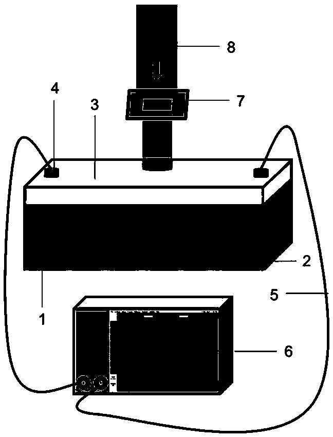
[0028] The optical and thermal detector of the present invention comprises an obliquely cut substrate, a transverse pyroelectric element, a metal electrode, and a lead wire connected to the metal electrode for outputting a voltage signal from bottom to top; Prepared on cut substrate c Strontium ruthenate thin films grown with tilted axis. The schematic diagram of the detector is shown in figure 1 shown.
[0029] The preparation of the detector includes the following steps:
[0030] 1. Prepare the target material by solid powder sintering method: mix and grind ruthenium oxide and strontium carbonate powder according to the molar ratio Ru:Sr=1:1, and then sinter with gradient temperature increase in the range of 600~1200°C, every 200°C increase Calcination once, 12 hours each time, after each calcinati...
Embodiment 2
[0037] Example 2 Detection of 1550nm near-infrared continuous laser light by photo-thermal detectors on strontium titanate substrates with strontium titanate obliquely cut at 5 degrees
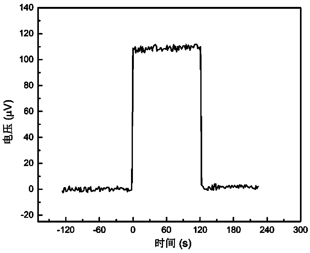
[0038] The central position of the detector surface designed in Example 1 is irradiated with a continuous laser with a wavelength of 1550 nm. Use a voltmeter to record the output voltage signal generated when the continuous laser light of 1550 nm is irradiated on the surface of the strontium ruthenate thin film light and heat detector as Figure 4 As shown, the output voltage signal amplitude of the strontium ruthenate thin-film detector prepared on the 5-degree skew-cut strontium titanate substrate is 37µV, and the sensitivity is high.
Embodiment 3
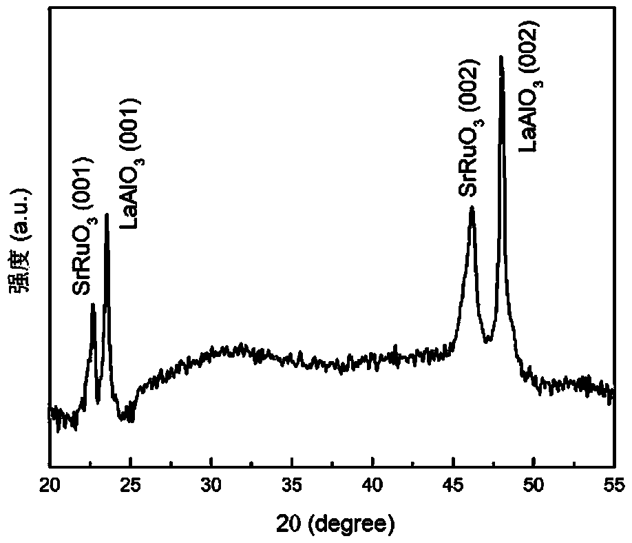
[0039] Example 3 Detection of 1550nm near-infrared continuous laser light by a strontium ruthenate thin film photo-thermal detector on a 10-degree beveled lanthanum aluminate substrate
[0040] 1. Replace the beveled 5-degree strontium titanate substrate in embodiment 1 with a beveled 10-degree lanthanum aluminate substrate, and other operations are the same as steps 1-4 in embodiment 1; high quality can be obtained cStrontium ruthenate (SrRuO) grown with tilted axis 3 ) thin film (the tilt angle is 10 degrees), the X-ray diffraction pattern of the obtained strontium ruthenate thin film thermoelectric element is as follows Figure 5 shown.
[0041] 2. Irradiate the center of the detector surface with a continuous light laser with a wavelength of 1550 nm. Use a voltmeter to record the output open-circuit voltage signal generated when the continuous laser light of 1550 nm is irradiated on the surface of the strontium ruthenate thin film photo-thermal detector, such as Figure...
PUM
| Property | Measurement | Unit |
|---|---|---|
| thickness | aaaaa | aaaaa |
| diameter | aaaaa | aaaaa |
| diameter | aaaaa | aaaaa |
Abstract
Description
Claims
Application Information
 - R&D Engineer
- R&D Manager
- IP Professional
- Industry Leading Data Capabilities
- Powerful AI technology
- Patent DNA Extraction
Browse by: Latest US Patents, China's latest patents, Technical Efficacy Thesaurus, Application Domain, Technology Topic, Popular Technical Reports.
© 2024 PatSnap. All rights reserved.Legal|Privacy policy|Modern Slavery Act Transparency Statement|Sitemap|About US| Contact US: help@patsnap.com