
Radio frequency particle source

A technology of particle source and radio frequency signal source, which is applied in the field of radio frequency particle source, can solve the problems such as the rise of cathode temperature, the influence of plasma source life, and the decrease of emission efficiency

Active Publication Date: 2020-07-07
UNIV OF ELECTRONIC SCI & TECH OF CHINA
View PDF7 Cites 6 Cited by
  • Summary
  • Abstract
  • Description
  • Claims
  • Application Information

AI Technical Summary

Problems solved by technology

[0003] The traditional radio frequency ion source neutralizer uses a hot cathode with an external electrode to emit electrons. In order to overcome the work function of the electrons, the cathode often needs a high working temperature. High temperature will increase the heat loss of the cathode and reduce the emission efficiency. bombardment, the temperature of the cathode will further increase; at the same time, the life of the tungsten wire cathode used in plasma processing is only about 200 hours, and the life of the cathode also greatly affects the life of the plasma source

Method used


Image

  • Radio frequency particle source
  • Radio frequency particle source
  • Radio frequency particle source

Examples


Embodiment Construction

[0022] The present invention will be further described below in conjunction with specific embodiments, wherein, the accompanying drawings are only for exemplary illustrations, and what is shown is only a schematic diagram rather than a physical map, and cannot be interpreted as a limitation to this patent; in order to better illustrate the implementation of the present invention For example, some components in the drawings may be omitted, enlarged or reduced, and do not represent the actual size; for those skilled in the art, it is understandable that some known structures and their descriptions in the drawings may be omitted.

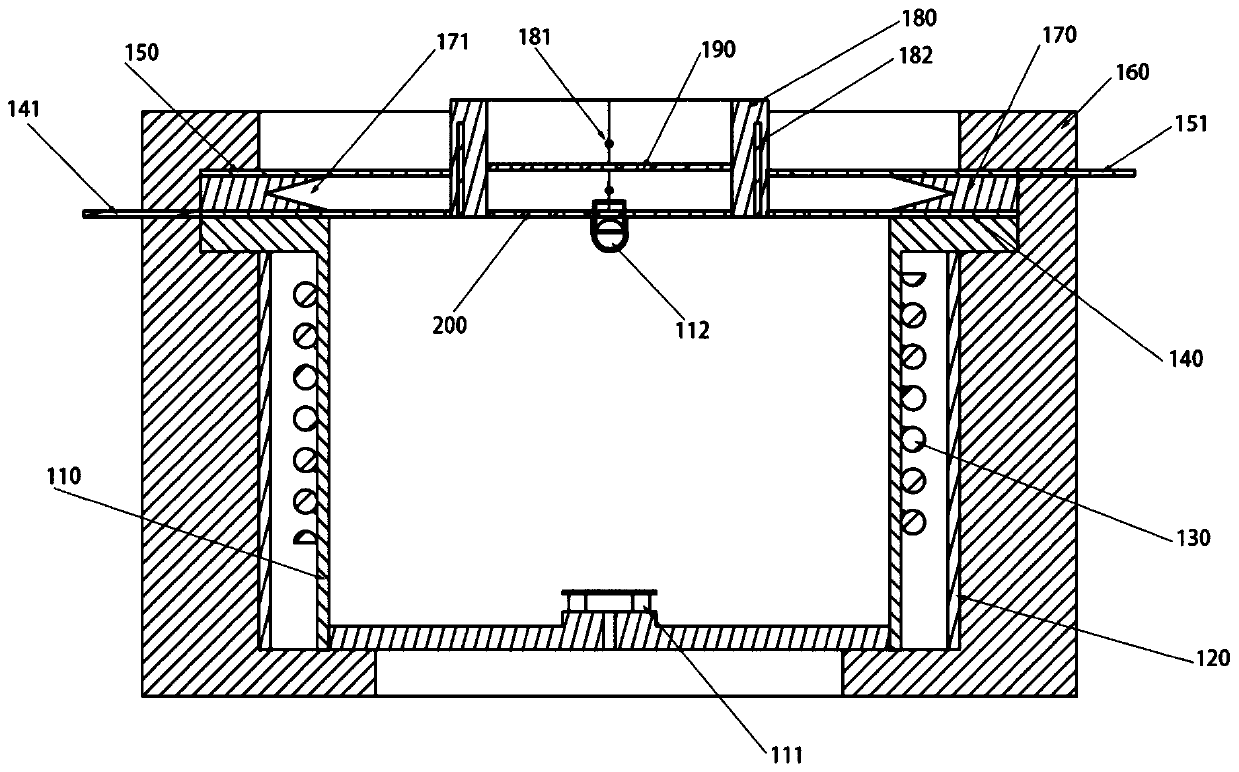
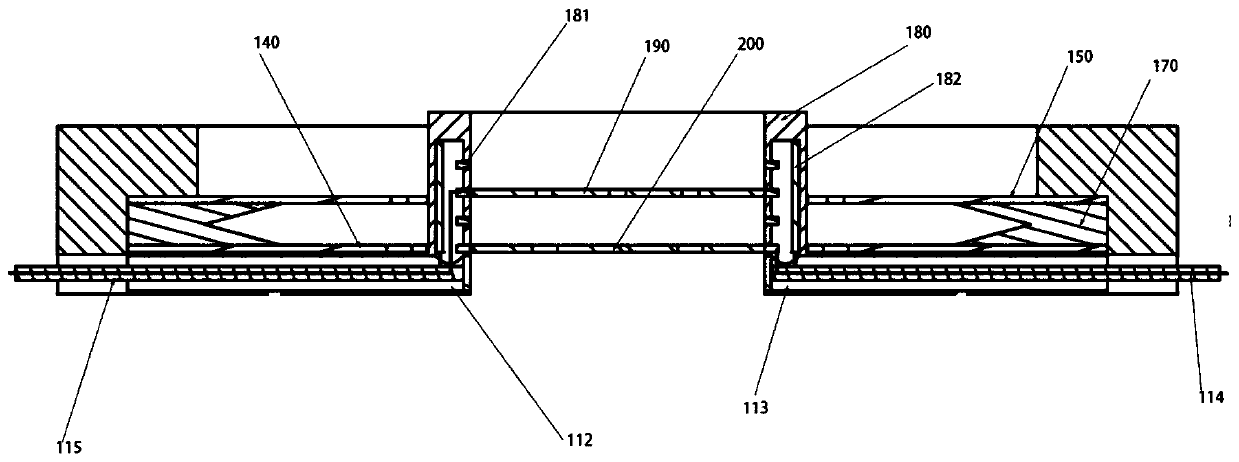
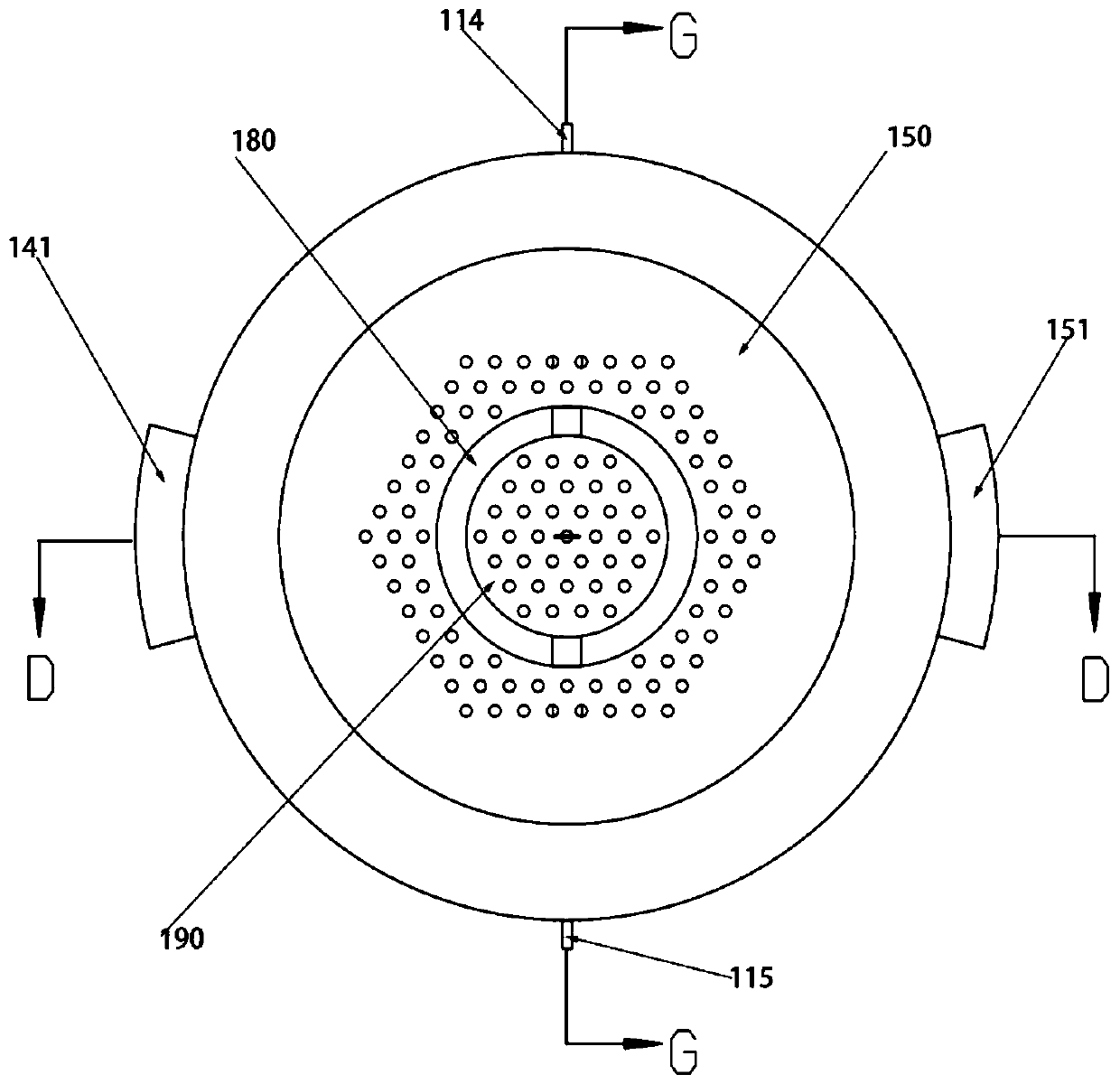
[0023] This embodiment provides a kind of non-neutralization radio frequency particle source, its structural diagram is as follows figure 1 shown, where:

[0024] The preferred material of the radio frequency discharge chamber 110 is: boron nitride ceramics, the bottom of the radio frequency discharge chamber 110 is provided with an air inlet 111, and ...


PUM


Abstract

The invention relates to the technical field of particle beam generation and neutralization, and particularly provides a radio frequency particle source. The radio frequency particle source comprisesa radio frequency signal source, an impedance matching network, a radio frequency coil, a radio frequency discharge cavity and a grid mesh system, wherein the grid mesh system comprises an inner layergrid mesh and an outer layer grid mesh; through voltage adjustment of the inner-layer grid mesh and the outer-layer grid mesh, ion beams and electron beams can be generated respectively, or the electron beams and the ion beams are generated simultaneously and neutralized to form neutral particle beams; and meanwhile, the beam positive and negative charge density and the particle movement speed are controlled and extracted by adjusting the grid distance and the grid electrode voltage, so that the beam particle density, speed and charge are adjustable. Besides, an external cathode and a corresponding electrode which need to be used by a traditional ion source for neutralizing the particle beam are not needed, the complexity of radio frequency ion source equipment is reduced to a great extent, the influence of high temperature of the cathode and sputtering on the service life of the ion source is avoided, and the stability of the beam generation effect is guaranteed.

Description

technical field [0001] The invention relates to the technical field of particle beam generation and neutralization, and more specifically, to a radio frequency particle source. Background technique [0002] Radio frequency plasma uses radio frequency energy to generate displacement current to ionize gas to form plasma. Conventional RF ion sources generate an RF plasma and extract a beam of ions from the ionized plasma. Radio frequency ion sources are widely used in material coating, nuclear fusion, aviation propulsion and other fields. The radio frequency ion source neutralizer emits electrons to the ion source beam, neutralizes the charge of the ion beam, and avoids the accumulation of the beam charge. It is an important component of the radio frequency ion source. [0003] The traditional radio frequency ion source neutralizer uses a hot cathode with an external electrode to emit electrons. In order to overcome the work function of the electrons, the cathode often needs ...

Claims


Application Information

Patent Timeline
IPC IPC(8): H05H1/46H01J27/18
CPCH01J27/18H05H1/46H05H1/4645
Inventor 袁学松朱昀泽鄢扬傅文杰李海龙王彬蒙林
Owner UNIV OF ELECTRONIC SCI & TECH OF CHINA
Learn More