Waste incineration flue gas cooling and quenching integrated device

A technology for incinerating flue gas and waste, which is applied in the field of waste incineration flue gas cooling and quenching integrated devices, which can solve the problems of complex phase composition, heavy weight of cooling and cooling devices, and reduced reliability, so as to improve the heat transfer effect , reduce the weight of the equipment, and improve the reliability

Pending Publication Date: 2020-06-30
上海工业锅炉(无锡)有限公司
View PDF0 Cites 3 Cited by
  • Summary
  • Abstract
  • Description
  • Claims
  • Application Information

AI Technical Summary

Problems solved by technology

Due to the high temperature of the incineration flue gas, usually the inlet temperature can reach 1100 ° C, and it has complex phase composition, and is affected by the heat exchange area and heat exchange efficiency, so the material used for the cooling device has a high resistance Due to high temperature and corrosion resistance requirements, high-grade heat-resistant stainless steel is required for the furnace wall and quenching water pipes, and refractory materials are required for the heat exchange pipe section under high temperature conditions, so the weight of the entire cooling and cooling device is heavy, and the reliability decreases after long-term use

Method used


Image

  • Waste incineration flue gas cooling and quenching integrated device

Examples


Embodiment Construction

[0023] The specific implementation manner of the present invention will be described below in conjunction with the accompanying drawings.

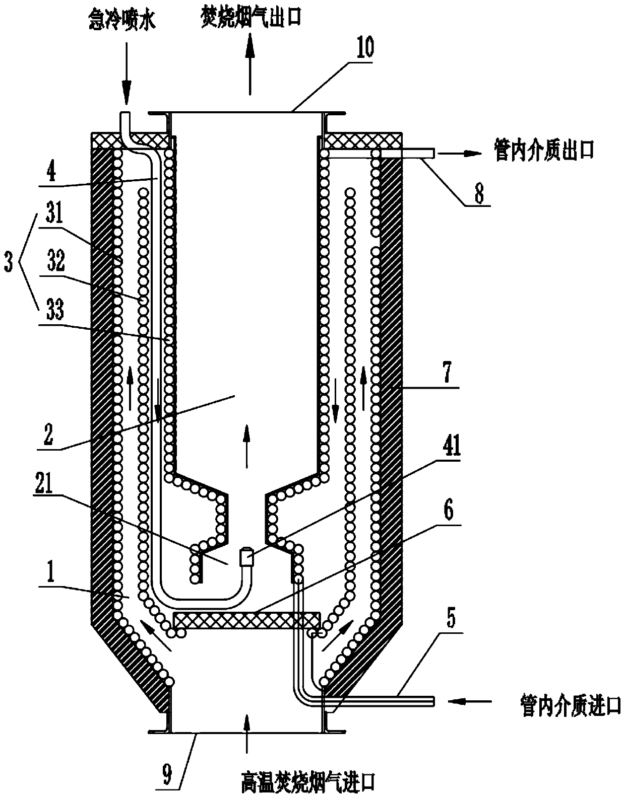
[0024] Such as figure 1 As shown, the waste incineration flue gas cooling and quenching integrated device of this embodiment includes a first furnace body 1, a high-temperature incineration flue gas inlet 9 is provided at the bottom, and a connecting hole is provided in the middle of the first furnace body 1. The second furnace body 2 with a reduced diameter has a cooled low-temperature incineration flue gas outlet 10 at the top, a furnace body inlet 21 at the bottom, and a diversion partition in the first furnace body 1 below the furnace body inlet 21 6;

[0025] It also includes a close-packed coil pipe 3, which is located between the inner wall of the first furnace body 1 and the outer wall of the second furnace body 2. The first coil 31 is arranged, and the inner ring of the first coil 31 is successively provided with the second coil...


PUM


Abstract

The invention relates to a waste incineration flue gas cooling and quenching integrated device. The waste incineration flue gas cooling and quenching integrated device comprises a first furnace body and densely-distributed coiled pipes, wherein a reduced-diameter second furnace body which communicates with the first furnace body is arranged in the first furnace body; the bottom of the second furnace body is provided with a furnace body inlet; a guide baffle is arranged in the first furnace body below the furnace body inlet; the densely-distributed coiled pipes include first coiled pipes whichare attached to an inner wall of the first furnace body and are closely arranged along a circumferential direction in a way of spirally extending in an axial direction; second coiled pipes and third coiled pipes which communicate with the first coiled pipes and are distributed in the same way are arranged on inner rings of the first coiled pipes in sequence; flue gas flow channels are formed between the first coiled pipes and the second coiled pipes, as well as between the second coiled pipes and the third coiled pipes; the third coiled pipes are closely arranged in a way of being attached toan outer wall of the second furnace body; a quenching water spray pipe is arranged between one of the second coiled pipes and one of the third coiled pipes; and two sides of a pipe wall of the quenching water spray pipe are close to pipe walls of the second coiled pipes and the third coiled pipes respectively. Through the adoption of the waste incineration flue gas cooling and quenching integrateddevice, the heat exchanging effect of a heat exchanging segment is improved; the requirements of fire resistance and high temperature resistance on materials of the heat exchanging segment and a quenching segment are lowered; and the running reliability is improved.

Description

technical field [0001] The invention relates to the technical field of high-temperature incineration flue gas cooling, in particular to a waste incineration flue gas cooling and rapid cooling integrated device. Background technique [0002] Whether it is solid waste, liquid waste, or gaseous waste, a certain amount of dioxin will be produced during the incineration process. The waste heat of the flue gas produces steam or hot water. When the temperature drops to no less than 600°C, rapid cooling is performed to avoid the re-generation of dioxins that have been decomposed at high temperatures. The rapid cooling method has flue gas recirculation Or spray water. Due to the high temperature of the incineration flue gas, usually the inlet temperature can reach 1100 ° C, and it has complex phase composition, and is affected by the heat exchange area and heat exchange efficiency, so the material used for the cooling device has a high resistance Due to high temperature and corrosi...

Claims


Application Information

Patent Timeline
Patent Type & Authority Applications(China)
IPC IPC(8): F28C1/14F28F25/00F28F25/06F23J15/06
CPCF23J15/06F28C1/14F28F25/00F28F25/06Y02E20/30
Inventor 陆屏陈弘
Owner 上海工业锅炉(无锡)有限公司
Why Eureka
Try Eureka