Eureka AIR delivers breakthrough ideas for toughest innovation challenges, trusted by R&D personnel around the world.

Vertical air conditioner indoor unit and air conditioner

A vertical air-conditioning indoor unit technology, applied in the field of air-conditioning, can solve the problems of low comfort and uneven indoor temperature distribution, and achieve the effects of improving comfort, preventing uneven temperature distribution, and improving temperature uniformity

Pending Publication Date: 2018-08-17
GREE ELECTRIC APPLIANCES INC
View PDF12 Cites 41 Cited by
  • Summary
  • Abstract
  • Description
  • Claims
  • Application Information

AI Technical Summary

Problems solved by technology

[0004] Therefore, the technical problem to be solved by the present invention is to overcome the shortcomings of the vertical air conditioner in the prior art that the indoor temperature distribution is uneven and the comfort level is not high, thereby providing a vertical air conditioner indoor unit and an air conditioner

Method used


Image

  • Vertical air conditioner indoor unit and air conditioner
  • Vertical air conditioner indoor unit and air conditioner
  • Vertical air conditioner indoor unit and air conditioner

Examples


Embodiment 1

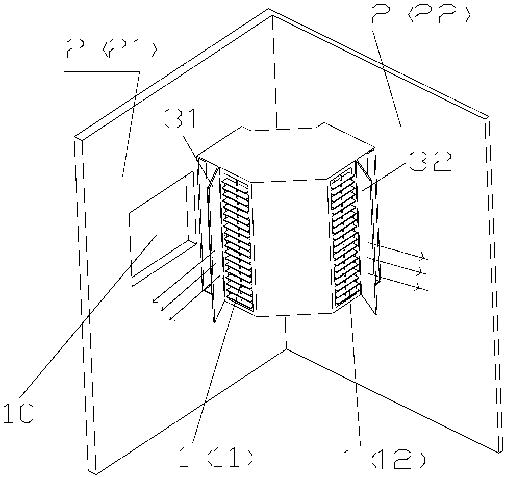
[0049] like Figure 1-4 As shown, the present invention provides a vertical air conditioner indoor unit (a vertical air conditioner generally refers to an air conditioner with a relatively long vertical direction), wherein the vertical air conditioner indoor unit 1 is installed at the indoor corner 2, and includes a first outlet An air outlet 11 and a second air outlet 12, and the first air outlet 11 can discharge air along the first wall 21 of the corner 2, and the second air outlet 12 can flow along the second wall of the corner 2 22 directions for air outlet.

[0050] In the present invention, the vertical air conditioner indoor unit is installed at the corner of the room, and the first air outlet can discharge air along the first wall direction of the corner, and the second air outlet can discharge air along the first wall direction of the corner. The air is blown in the direction of the second wall, so that the airflow sent by the left and right air outlets can flow alon...

Embodiment 2

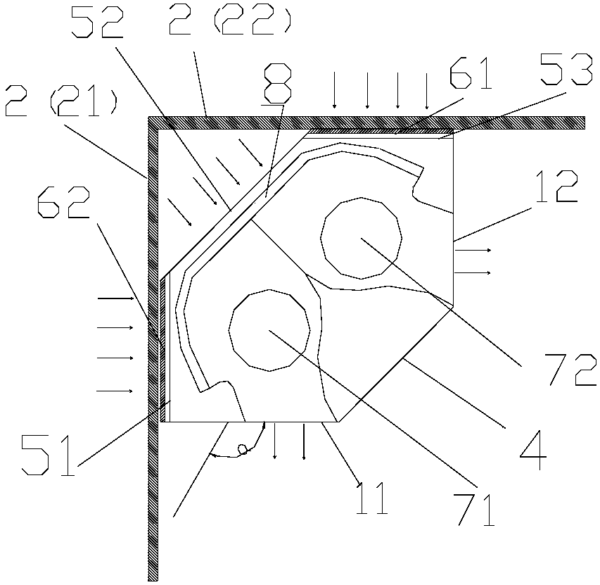
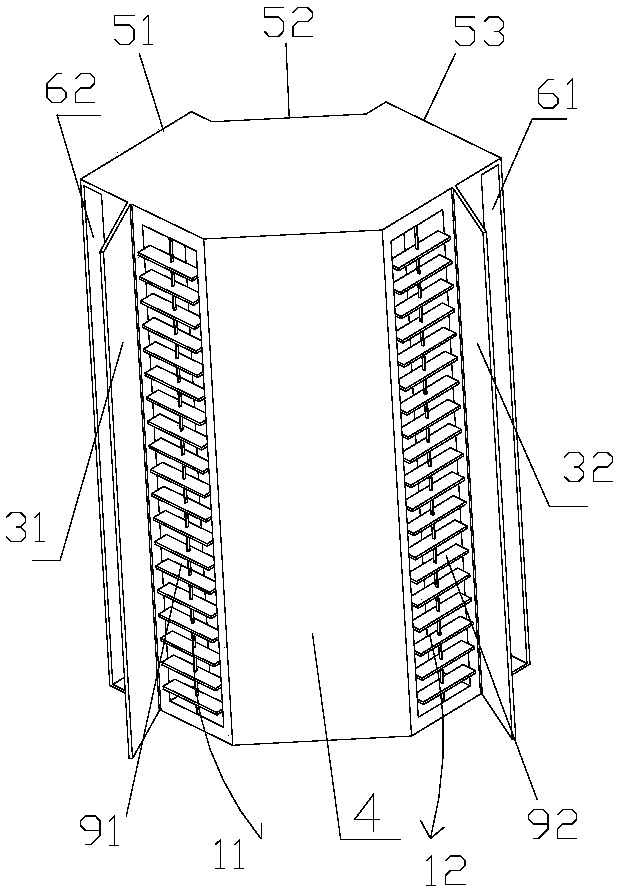
[0063] Such as Figure 5-8 As shown, this embodiment is a further improvement made on the basis of Embodiment 1, preferably, it also includes a first air inlet 51, a second air inlet 52 and a third air inlet 53, the second air inlet 52 Located between the first air inlet 51 and the third air inlet 53, the second air inlet 52 is opposite to the corner of the wall corner, the first air inlet 51 is opposite to the first wall 21, The third air inlet 53 is opposite to the second wall 22 .

[0064] Through the three air inlets, the air inlet area can be effectively increased, and the heat exchange area and heat exchange effect can be improved. Schematic such as figure 2 with Figure 4 shown. The two air outlets are located on the left and right sides of the panel 4, called the first and second air outlets. For aesthetics and safety, the first and second air outlets can be connected with the panel by circular arcs. The three air inlets are all distributed behind the air conditi...


PUM


Abstract

The invention provides a vertical air conditioner indoor unit and an air conditioner. The vertical air conditioner indoor unit (1) is installed at the position of an indoor wall corner (2) and comprises a first air outlet (11) and a second air outlet (12), the first air outlet (11) can conduct air outlet in the direction of a first wall face (21) of the wall corner (2), and the second air outlet (12) can conduct air outlet in the direction of a second wall face (22) of the wall corner (2). By means of the vertical air conditioner indoor unit and the air conditioner, airflow sent from the leftand right air outlets can flow along the wall, the air conditioner is prevented from blowing a person directly, the left and right air outlets achieve air supply along the wall, surrounding airflow can be achieved, the airflow achieves systemic circulation indoors, the coanda effect of the airflow is conveniently formed, even temperature distribution caused by uneven indoor airflow is prevented, the indoor temperature distribution is even, and the comfort of the user is improved.

Description

technical field [0001] The invention belongs to the technical field of air conditioners, and in particular relates to a vertical air conditioner indoor unit and an air conditioner. Background technique [0002] At present, most household wall-mounted air conditioners are hung horizontally on the wall, and the distance from the ground is very high. Provide good comfort; most of the existing vertical air conditioners are floor-standing for indoor air conditioning. With the rise of existing housing prices, vertical air conditioners that hang on the wall and do not occupy floor space are becoming more and more popular However, the existing vertical air conditioner has a single air outlet form, directly blows people, and cannot avoid people well, the indoor temperature distribution is uneven, and the comfort is not high; the existing vertical air conditioner occupies an area of ​​about 0.5m 2 The space occupied is relatively large, and the installation of vertical wall-mounted a...

Claims


Application Information

Patent Timeline
Patent Type & Authority Applications(China)
IPC IPC(8): F24F1/00F24F13/14F24F13/20
CPCF24F1/0007F24F13/14F24F13/20
Inventor 刘鹏陈志伟陈英强张兴钰向新贤
Owner GREE ELECTRIC APPLIANCES INC
Why Eureka
Eureka Blog
Learn More