an etching method
An over-etching, metal conductor technology, used in electrical components, circuits, semiconductor/solid-state device manufacturing, etc., can solve the problems of metal filler peeling, affecting the quality of metal wire channels and welding areas, and filling conductor resistance offset. , to reduce the adhesion, solve the peeling of metal fillers, and widen the discharge channel.
- Summary
- Abstract
- Description
- Claims
- Application Information
AI Technical Summary
Problems solved by technology
Method used
Image

Examples
Embodiment 1
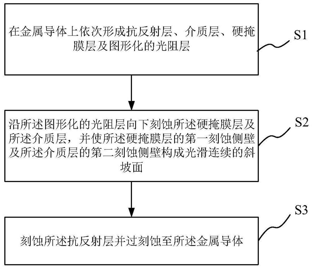
[0067] This embodiment provides an etching method, which includes the above steps S1-S3. Combine below Figure 3a-Figure 3d The specific description of each step is as follows:
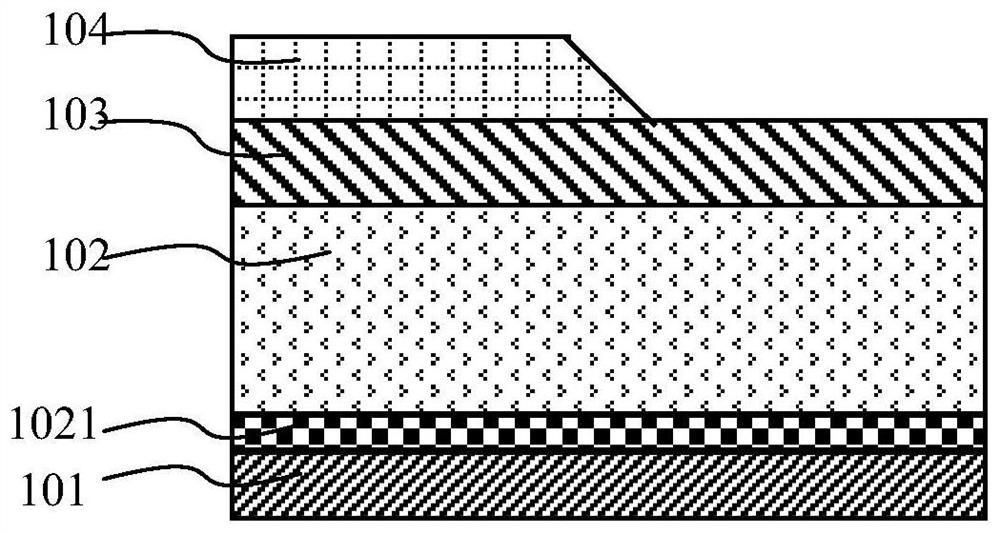
[0068] Such as Figure 3a As shown, a substrate to be etched is formed in step S1 , and the substrate includes a metal conductor 101 , a dielectric layer 102 to be etched, a hard mask layer 103 and a patterned photoresist layer 104 . The dielectric layer 102 to be etched is located above the metal conductor 101 , the hard mask layer 103 is located above the dielectric layer 102 , and the photoresist layer 104 is located above the hard mask layer 103 . Wherein, the metal conductor 101 may be a metal wire layer including one or more layers of metal materials, or may be a functional layer containing metal materials for other purposes. The dielectric layer 102 to be etched may be an oxide layer as an insulating medium, or other functional dielectric layers. An anti-reflection layer 1021 is also provid...
Embodiment 2
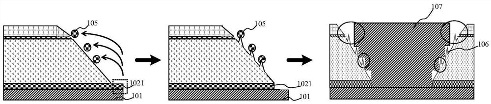
[0075] This embodiment provides an etching method, which is substantially the same as that of Embodiment 2, and the difference lies in the specific parameters in step S3. In order to discharge metal by-products 105 more quickly and timely, this embodiment increases the N 2 flow, and adjust the pressure of the reaction chamber, thereby further increasing the air flow in the reaction chamber.
[0076] Specifically, when performing overetching to the metal conductor 101 in step S3, a protective gas N 2 , reaction gas CHF 3 、CF 4 and O 2 , where N 2 The flow rate is 200-600sccm, CHF 3 The flow rate is 180-400sccm, CF 4 The flow rate is 200-400sccm, O 2 The flow rate is 30-80sccm, the air pressure is 30-200mTorr, the output power of the main RF source is 500-1500W, the frequency is 60MHz, the output power of the bias RF source is 1000-2000W, the frequency is 13MHz, and the heating temperature is 30-45 ℃.
Embodiment 3
[0078] This embodiment provides an etching method, which includes steps S1-S3. Before etching the hard mask layer 103 and the dielectric layer 102, the photoresist layer 104 is subjected to plasma treatment to increase the size of the photoresist layer 104. The slope of the sidewall facilitates the discharge of metal by-products 105 generated by over-etching. Combine below Figure 4a-Figure 4c The specific description of each step is as follows:
[0079] Such as Figure 4a As shown, a substrate to be etched is formed in step S1 , and the substrate includes a metal conductor 101 , a dielectric layer 102 to be etched, a hard mask layer 103 and a patterned photoresist layer 104 . The dielectric layer 102 to be etched is located above the metal conductor 101 , the hard mask layer 103 is located above the dielectric layer 102 , and the photoresist layer 104 is located above the hard mask layer 103 . An anti-reflection layer 1021 is also provided between the metal conductor 101 a...
PUM
 Abstract
Description
Claims
Application Information
 - R&D
- Intellectual Property
- Life Sciences
- Materials
- Tech Scout
- Unparalleled Data Quality
- Higher Quality Content
- 60% Fewer Hallucinations
Browse by: Latest US Patents, China's latest patents, Technical Efficacy Thesaurus, Application Domain, Technology Topic, Popular Technical Reports.
© 2025 PatSnap. All rights reserved.Legal|Privacy policy|Modern Slavery Act Transparency Statement|Sitemap|About US| Contact US: help@patsnap.com