
A reactive ion etching method and device

A technology of reactive ion etching and equipment, applied in the direction of circuits, discharge tubes, electrical components, etc., can solve the problems of small plasma kinetic energy, large equipment volume, difficulty reaching the bottom of deep holes or deep grooves, etc., to improve selectivity, The effect of increasing the etching rate and improving the etching morphology

Active Publication Date: 2019-08-27
YANGTZE MEMORY TECH CO LTD
View PDF6 Cites 0 Cited by
  • Summary
  • Abstract
  • Description
  • Claims
  • Application Information

AI Technical Summary

Problems solved by technology

However, based on the existing plasma generation methods, if the plasma density needs to be further increased, a higher discharge voltage is required. In this way, the requirements for the radio frequency output power and heat load of the plasma generation equipment are higher, and the equipment volume is larger.
[0005] In addition, for the etching of deep holes or deep trenches with high aspect ratios, the plasma kinetic energy in conventional reactive ion etching is relatively small, and it is difficult to reach the bottom of deep holes or deep trenches and continue to etch downward rapidly

Method used


Image

  • A reactive ion etching method and device
  • A reactive ion etching method and device

Examples


Embodiment Construction

[0046] Specific embodiments of the present application will be described in detail below in conjunction with the accompanying drawings.

[0047] Firstly, the specific implementation of the reactive ion etching equipment for implementing the reactive ion etching method provided in this application will be introduced.

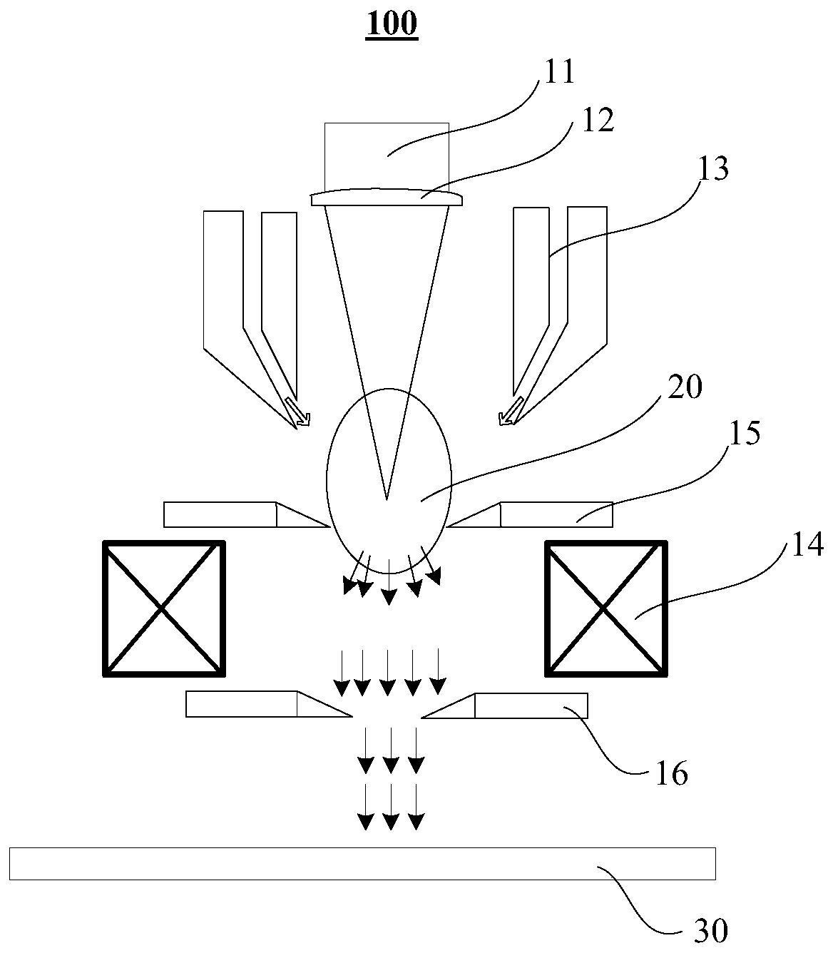
[0048] See figure 1 . The reactive ion etching equipment 100 includes: a pulsed laser source 11 , a focusing lens 12 , a reactive gas nozzle 13 and an ion deflection magnetic lens 14 .

[0049] Among them, the pulsed laser source 11 is used to generate pulsed laser; as a specific embodiment of the present application, in order to improve the ionization degree of the reaction gas, the density of the generated plasma and the initial kinetic energy of the plasma, the pulsed laser source 11 can be a high-frequency pulse laser source. As an example, the frequency of the pulsed laser source 11 may be greater than 10 kHz. As an example, the pulsed laser source 11 ma...


PUM


Abstract

The invention discloses reaction ion etching method and equipment. According to the method, plasma for reaction ion etching is produced based on a pulse laser induction mode rather than a radio frequency discharging mode. Compared with radio frequency discharging under a certain voltage, a gas is easier to generate plasma by pulse laser focusing, the ionization degree is higher, thus, compared with the radio frequency discharging mode under the certain voltage, the pulse laser induction mode has the advantages that the plasma which can be produced is larger in density, and the formed plasma islarger in initial kinetic energy. With the adoption of the pulse laser mode, the reaction ion etching rate can be favorably improved, and bottom etching of a deep hole or a deep groove is particularly facilitated; and moreover, the produced plasma is larger in density and initial kinetic energy, thus, the selectivity of anisotropic etching is favorably improved through etching by employing the plasma produced by the mode, and the etching morphology is favorably improved.

Description

technical field [0001] The present application relates to the technical field of reactive ion etching, in particular to a reactive ion etching method and equipment. Background technique [0002] The reactive ion etching method mainly performs physical and chemical reactions on the medium through the directional active free radicals in the plasma, so as to achieve rapid anisotropic etching. [0003] Existing reactive plasmas mainly include the following types: Inductively Coupled Plasma (ICP), Capacitively Coupled Plasma (CCP) and Electron Cyclotron Resonance (ECR). These types of plasmas are based on radio frequency discharge (Discharge Produced Plasma, DPP), and their plasma density is usually 10 10 ~10 12 cm -3 . [0004] According to the etching mechanism of reactive ions, it can be known that the greater the plasma density in the reactive ion plasma etching process, the more active radicals are, which is more conducive to increasing the etching rate. However, based ...

Claims


Application Information

Patent Timeline
Patent Type & Authority Patents(China)
IPC IPC(8): H01J37/32
Inventor 陈子琪
Owner YANGTZE MEMORY TECH CO LTD
Learn More