
Radiative cooling film and production method and application thereof

A radiative cooling and film technology, applied in the field of radiative cooling film and its preparation, can solve the problems of reducing solar radiation reflectivity, earth environment and biological damage, greenhouse effect and air pollution, etc., to achieve improved safety performance, excellent transparency, The effect of excellent physical and mechanical properties

Pending Publication Date: 2020-02-04
厦门银蚁新能源科技有限公司
View PDF8 Cites 7 Cited by
  • Summary
  • Abstract
  • Description
  • Claims
  • Application Information

AI Technical Summary

Problems solved by technology

However, due to the relatively large particle size of the particles, it is easy to form a rough surface with obvious concavities and convexities on the composite film. Direct coating on the surface of such a composite film will affect the optical quality of the coating and reduce the reflectivity of solar radiation.
In addition, the polymer matrix materials used are all non-degradable materials, which are easy to burden the environment
Because it is discarded after being used once, the reuse rate is very low, which will cause huge energy loss and environmental pollution.
The main ways for humans to deal with plastic waste are incineration and landfill. Combustion will cause greenhouse effect and air pollution, while landfill and ocean landfill are easy to cause harm to the earth's environment and organisms
According to reports, it takes about 500 years for general plastic landfills to completely degrade. Plastic pollution will not only affect the ecological environment, but also cause great harm to humans.

Method used


Image

  • Radiative cooling film and production method and application thereof
  • Radiative cooling film and production method and application thereof

Examples


Embodiment 1

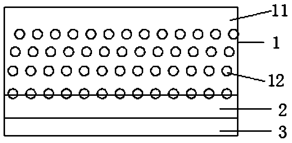
[0053] refer to figure 1 , a radiation cooling film, which is composed of a radiation cooling layer 1, a smooth layer 2 and a reflection layer 3 in sequence, and the thicknesses are 45 microns, 5 microns, and 0.04 microns in sequence.

[0054] Wherein, the radiation cooling layer 1 comprises a polylactic acid resin matrix 11 and particles 12 dispersed in the polylactic acid resin matrix 11, the polylactic acid resin matrix 11 comprises polylactic acid, a coupling agent and a light stabilizer, and the amount of each substance in the radiation cooling layer 1 is It is: 94 parts by weight of polylactic acid, 6 parts by weight of microparticles 12, 0.03 parts of coupling agent, and 0.15 parts of light stabilizer. The coupling agent is silane coupling agent KH560, and the light stabilizer is UV326.

[0055] Particles 12 are silicon dioxide and have a size of 4±2 microns. The surface of the radiative cooling layer 1 near the smooth layer 2 is uneven due to the dispersed presence o...

Embodiment 2

[0057] A radiation cooling film is composed of a radiation cooling layer 1, a smooth layer 2 and a reflection layer 3 in sequence, and the thicknesses are 65 microns, 14 microns and 0.15 microns in sequence.

[0058] Wherein, the radiation cooling layer 1 comprises a polylactic acid resin matrix 11 and particles 12 dispersed in the polylactic acid resin matrix 11, the polylactic acid resin matrix 11 comprises polylactic acid, a coupling agent and a light stabilizer, and the amount of each substance in the radiation cooling layer 1 is It is: 82 parts by weight of polylactic acid, 18 parts by weight of microparticles 12, 0.18 parts of coupling agent, and 0.1 part of light stabilizer. The coupling agent is silane coupling agent KH550, and the light stabilizer is UV326 and UV5050.

[0059] The particle 12 is a mixture of silicon dioxide and silicon carbide, the size of which is 15±2 microns, and the mass ratio of the two is 3:2. The surface of the radiative cooling layer 1 near t...

Embodiment 3

[0061] A radiation cooling film is composed of a radiation cooling layer 1, a smooth layer 2 and a reflection layer 3 in sequence, and the thicknesses are 50 microns, 10 microns and 0.1 microns in sequence.

[0062] Wherein, the radiation cooling layer 1 comprises a polylactic acid resin matrix 11 and particles 12 dispersed in the polylactic acid resin matrix 11, the polylactic acid resin matrix 11 comprises polylactic acid, a coupling agent and a light stabilizer, and the amount of each substance in the radiation cooling layer 1 is It is: 90 parts by weight of polylactic acid, 10 parts by weight of microparticles 12, 0.05 parts of coupling agent, and 1 part of light stabilizer. The coupling agent is silane coupling agent KH550, and the light stabilizer is UV326 and UV329 mixed in a mass ratio of 1:1.

[0063] The particle 12 is a mixture of silicon dioxide and aluminum oxide, the size of which is 10±2 microns, and the mass ratio of the two is 4:1. The surface of the radiativ...


PUM

PropertyMeasurementUnit
Thicknessaaaaaaaaaa

Abstract

The invention relates to a radiative cooling film and a production method and application thereof. The radiative cooling film comprises a radiative cooling layer, a flat and smooth layer and a reflection layer which are sequentially arranged, wherein the radiative cooling layer comprises polylactic resin, cooling particles, a coupling agent and a light stabilizer, the surface, close to one side ofthe flat and smooth layer, of the radiative cooling layer is uneven, the flat and smooth layer and the radiative cooling layer fit closely, and the surface, close to one side of the reflection layer,of the flat and smooth layer is flat and smooth. According to the radiative cooling film and the production method and application thereof, the radiative cooling layer and the flat and smooth layer are produced by means of a casting and co-extrusion technology, and the reflection layer is produced by means of vacuum evaporation aluminizing; and the mean reflectance of the radiative cooling film in all the wave bands of 300-2500 nanometers is equal to or larger than 95%, the infrared emitting ability E in the wave band of 8-13 micrometers is equal to or larger than 92%, radiative cooling powerP in direct sunlight is equal to or larger than 100 W / m<2>, a product has degradation performance, and a degradation rate, measured by soil burial experiment, of the product can reach 69%.

Description

technical field [0001] The invention relates to a functional thin film material, especially a radiation cooling thin film and its preparation method and application. Background technique [0002] Passive diurnal radiative cooling refers to the phenomenon that an object cools its surface by reflecting sunlight and radiating heat to the cold space. More and more attention has been paid to the advantages of efficient cleaning. [0003] The way to enhance the radiative cooling capacity is to increase the reflectivity of the surface of the object to solar radiation (with a wavelength between 0.3-2.5 microns) and to enhance the infrared emissivity of the transparent atmospheric window spectrum (8-13 microns) as much as possible. Ordinary objects are often difficult to have the above two properties at the same time, or the absorption of solar radiation is relatively large, or the infrared radiation ability in the atmospheric window is weak, which leads to the fact that the object ...

Claims


Application Information

Patent Timeline
IPC IPC(8): B32B27/06B32B27/36B32B27/20B32B33/00C08L67/04C08K9/06C08K3/36C08K3/22C08K3/34C08J5/18B29B7/28B29B7/82B29C48/92B29D7/01F25B23/00
CPCB29B7/28B29B7/823B29D7/01B32B27/08B32B27/20B32B27/36B32B33/00B32B2250/02B32B2255/10B32B2255/205B32B2307/30B32B2307/716B32B2307/746B29C48/92B29C2948/9258B29C2948/92704C08J5/18C08J2367/04C08K3/34C08K3/36C08K9/06C08K2003/2227C08K2201/003F25B23/003F28F13/18
Inventor 陈剑洪林娜杨戈尔付鑫
Owner 厦门银蚁新能源科技有限公司
Learn More