
Luminaire for Indoor Horticulture

a technology for indoor horticulture and luminaires, which is applied in the direction of lighting devices, lighting and heating equipment, lighting devices details, etc., can solve the problems of reducing the effective reflecting area of the reflector portion of the luminaire, inconvenient operation, and typically no provision for controlling the air flow path through the luminaire, and achieves high transparency

Inactive Publication Date: 2013-04-04
DIMITRIADIS THOMAS C
View PDF8 Cites 114 Cited by
  • Summary
  • Abstract
  • Description
  • Claims
  • Application Information

AI Technical Summary

Benefits of technology

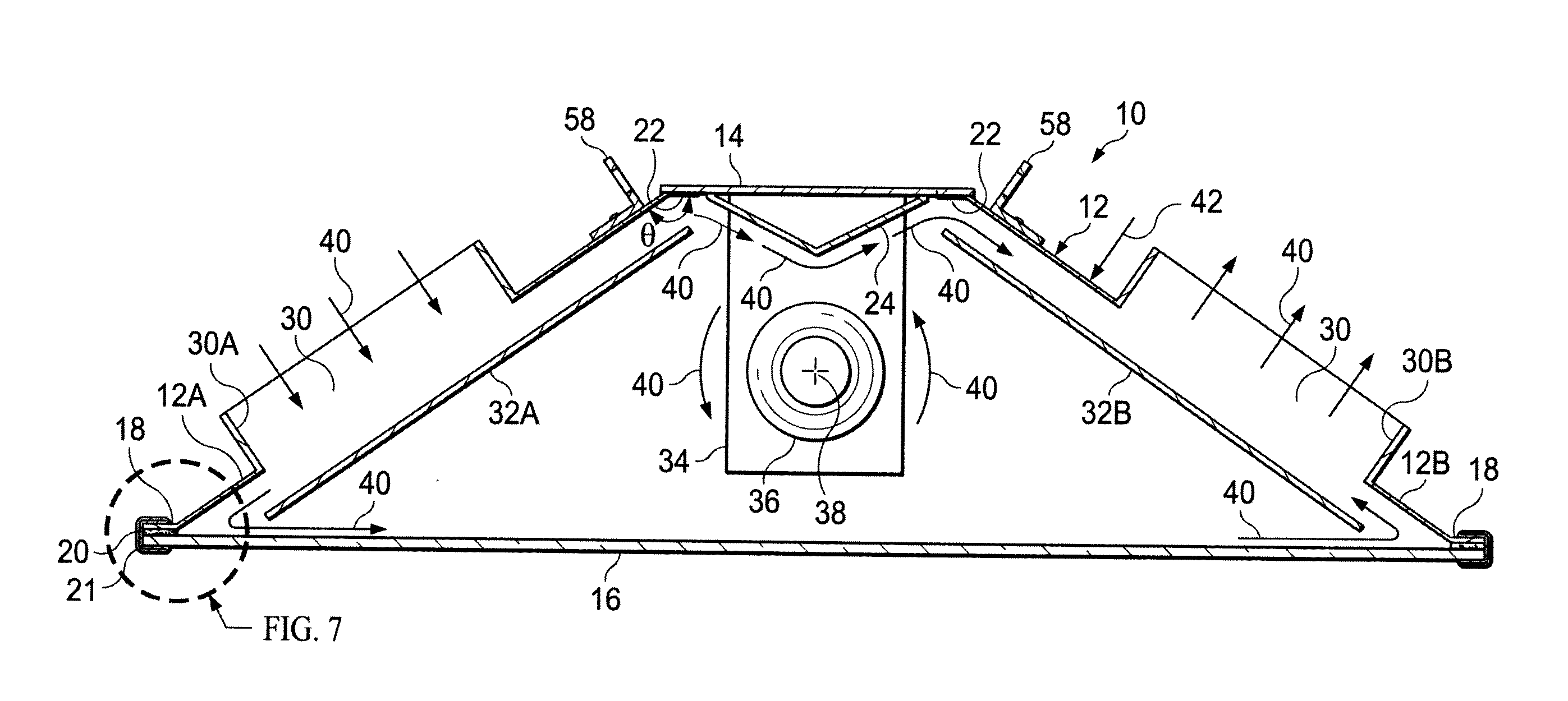
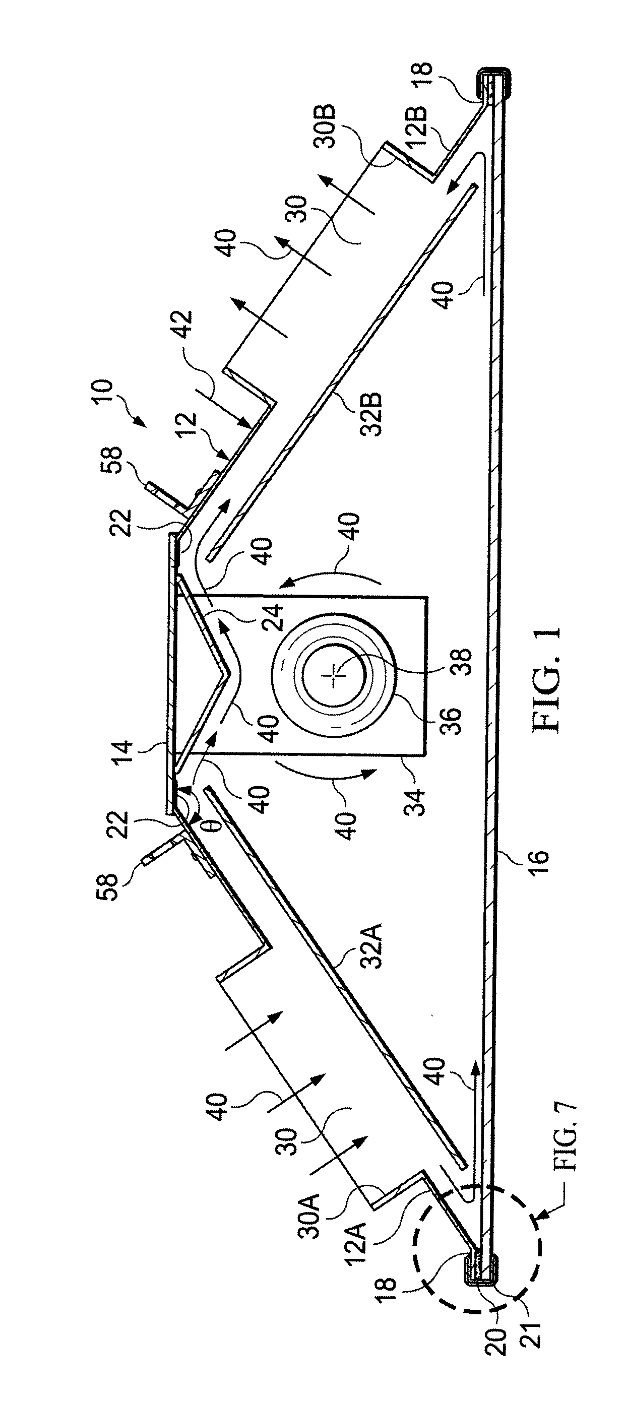
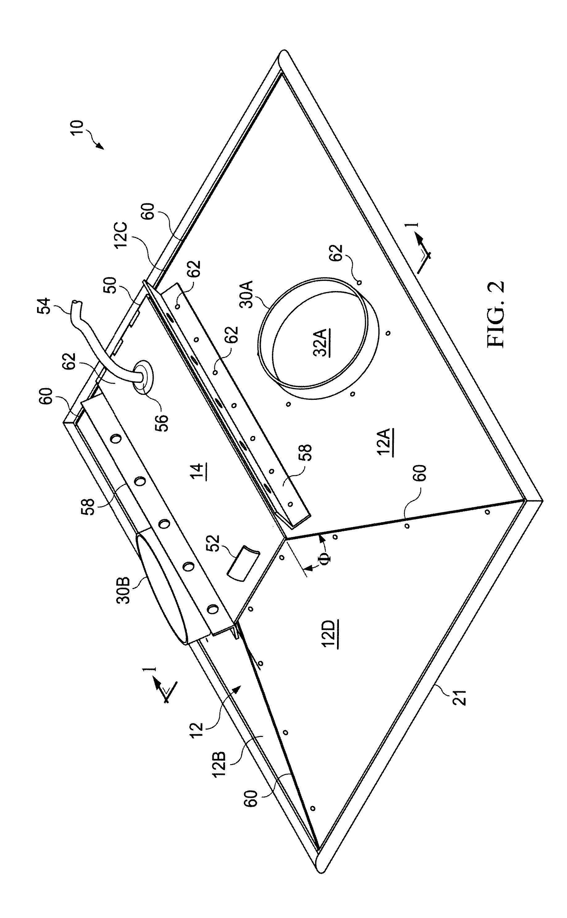
The patent describes a reflector for a luminaire that includes a rectangular hood-like exterior shell with air flow ducts on its sides. The shell also has first and second secondary reflecting panels that reflect light from a lamp inside the luminaire instead of passing through the air flow ducts. The design allows for easy access to the lamp assembly through a top opening and a ventilated reflector for an indoor luminaire is also provided. The reflector panels and duct openings improve the lighting efficiency of the luminaire.

Problems solved by technology

Steel is heavier than aluminum, and painted surfaces that require an extra step in manufacture provide only moderate reflectivity for use in light fixtures such as the luminaires used in indoor horticulture.
Further, while the inlet / outlet ducts of this arrangement can indeed remove heat emitted by the lamp, the area of the duct openings, which pass through a substantial portion of the reflecting surface, is lost thereby reducing the effective reflecting area of the reflector portion of the luminaire.
Moreover, there is typically no provision for controlling the air flow path through the luminaire to gain maximum efficiency of ventilation to reduce the amount of heat radiated into the plants.
Other attributes of conventional designs is the need to remove the glass lens to access the lamp assembly to replace the lamp, an inconvenient operation at best.
Additionally, in the typical luminaire, the glass lens, though tempered for safety, is typically soda lime glass that is inexpensive but has less than optimum transparency.
The foregoing characteristics of conventional luminaires used for indoor horticulture result in reduced efficiencies in operation.

Method used


Image

  • Luminaire for Indoor Horticulture
  • Luminaire for Indoor Horticulture
  • Luminaire for Indoor Horticulture

Examples


Embodiment Construction

[0020]In an advance in the state of the art of luminaires for indoor horticulture the description of the invention herein below, read in conjunction with the included drawings, describes a ventilated reflector for an indoor luminaire or lighting fixture having novel ventilation and illumination features that provide improved utility and efficiency in operation. The embodiment described is intended to be illustrative of the principles employed to achieve the benefits of the improved design, and is not intended to be limiting of the scope of the invention. These principles may be applied to luminaires in a variety of applications and sizes without departing from the basic concept as described. In the several views provided in the drawings, structures bearing the same reference numbers are the same structural feature.

[0021]The embodiments of the invention described herein and set forth in the appended claims provide full reflecting surfaces within the full internal area of the exterior...


PUM


Abstract

A reflector hood for a luminaire having a lamp in an upper portion thereof and first and second air flow ducts formed in first and second opposite sides of said reflector hood for ventilation. First and second secondary reflecting panels are respectively disposed within the hood over and spaced a predetermined distance from each first and second air flow duct such that light emitted by the lamp is reflected from said reflecting panels instead of passing through the first and second air flow ducts.

Description

CROSS REFERENCE TO RELATED APPLICATION[0001]The present application claims priority from the earlier filed provisional application Ser. No. 61 / 626,580, filed Sep. 29, 2011, entitled “Sun Simulating Luminaire (lighting fixture) for Indoor Horticulture, by the same inventor.BACKGROUND OF THE INVENTION[0002]1. Field of the Invention[0003]The present invention generally relates to indoor lighting fixtures and more specifically to a reflector design for luminaires used in indoor horticulture.[0004]2. Background of the Invention and Description of the Prior Art[0005]Indoor horticulture requires exposure of plants to a light source that matches the characteristics of sunlight in both spectral and intensity aspects. These aspects should preferably be provided by sources that are as efficient as possible to conserve energy and avoid harm to the plants. Moreover, the choice of light source and design features of the reflector portions of the luminaire must be balanced against the outputs of a...

Claims


Application Information

Patent Timeline
Patent Type & Authority Applications(United States)
IPC IPC(8): F21V13/04F21V7/22F21V7/00
CPCF21V7/00F21V7/22F21V29/83F21V29/60F21V13/04F21V7/24
Inventor DIMITRIADIS, THOMAS C.
Owner DIMITRIADIS THOMAS C
Learn More