
Welding method for vacuum electronic bundle of aluminum alloy water cooling joint

A technology of vacuum electron beam and welding method, applied in electron beam welding equipment, welding equipment, metal processing equipment, etc., can solve the problems of low surface tension, high melting point, surface depression, etc., and achieve uniform weld formation and high power density. , The effect of welding deformation is small

Inactive Publication Date: 2019-12-13
SHENYANG FORTUNE PRECISION EQUIP CO LTD
View PDF5 Cites 1 Cited by
  • Summary
  • Abstract
  • Description
  • Claims
  • Application Information

AI Technical Summary

Problems solved by technology

For small size welds, welding processes such as MIG, TIG, FSW cannot be realized
Moreover, the aluminum alloy surface has a dense oxide film, high melting point, fast heat conduction, and difficult welding
For aluminum alloys containing Mg elements, during the LBW welding process, due to the volatilization of Mg elements, the surface tension is low, resulting in surface explosion points, surface depressions, internal pores and other defects, and the aluminum alloy has a low absorption rate of laser light, so welding Aluminum requires more power than welding steel

Method used


Image

  • Welding method for vacuum electronic bundle of aluminum alloy water cooling joint
  • Welding method for vacuum electronic bundle of aluminum alloy water cooling joint
  • Welding method for vacuum electronic bundle of aluminum alloy water cooling joint

Examples


Embodiment Construction

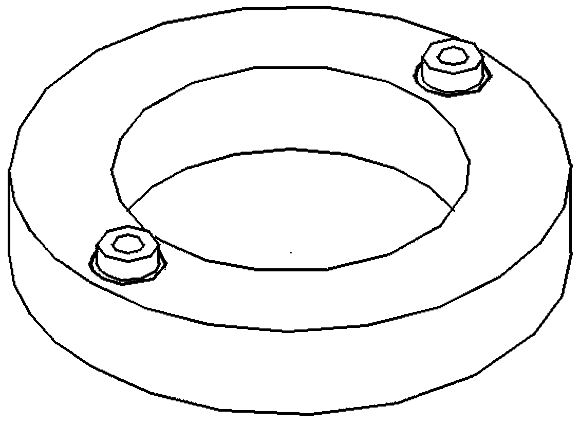
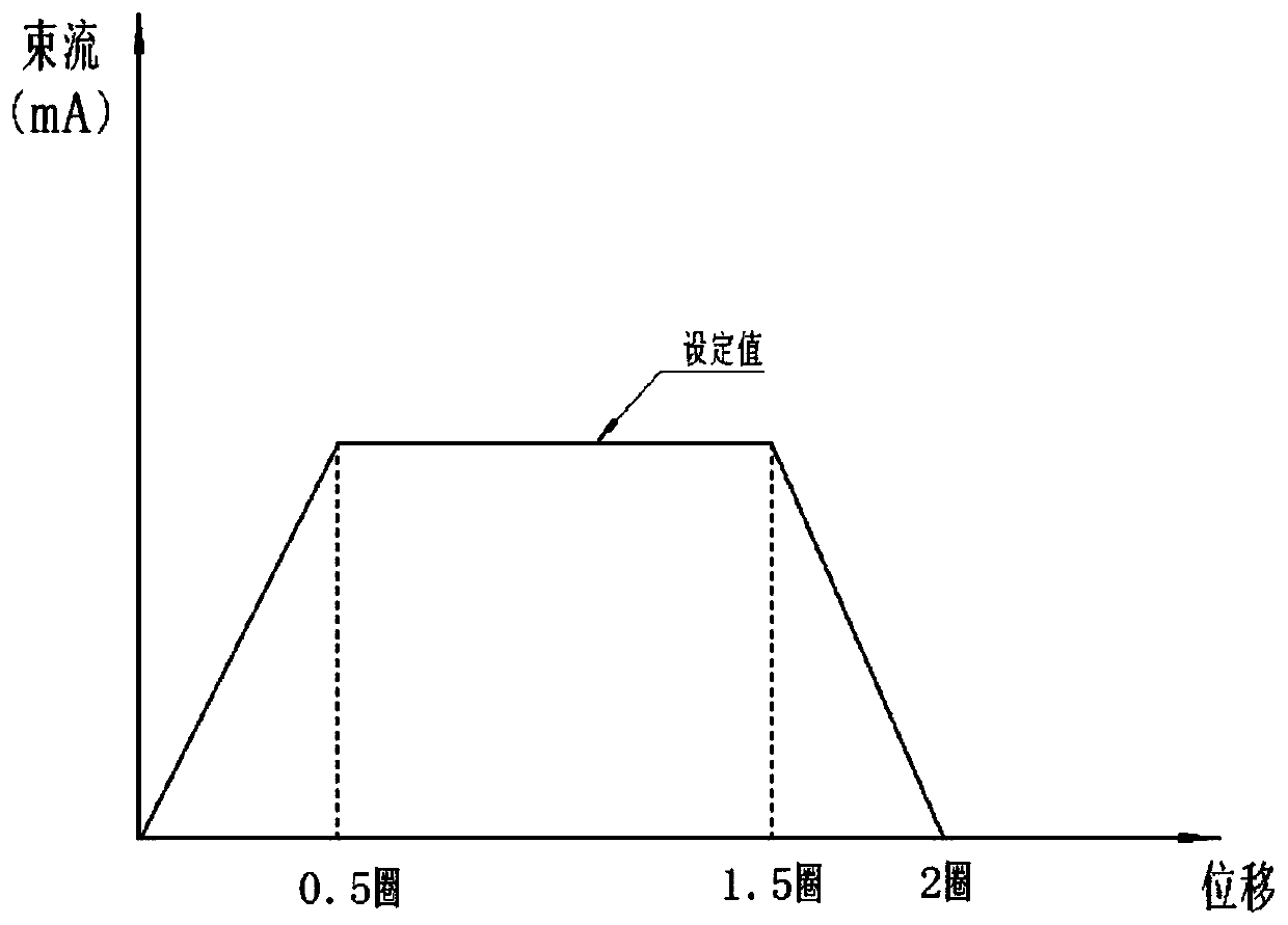
[0023] combined with Figure 1-3 The present invention is further described in detail.

[0024] A vacuum electron beam welding method for an aluminum alloy water-cooled joint, comprising the following steps:

[0025] The first step: chemically clean the workpiece and solder, clean in 25% NaOH for 3 minutes, and then in 15% HNO 3 +0.5% HF mixed solution to wash for 1min, and finally rinse with clean water.

[0026] The second step: drying, heat preservation in a drying oven at 120°C for 1 hour.

[0027] Step 3: Preset the solder into the assembly gap of the parts, the assembly gap is 0.4-0.6mm, the thickness of the solder is 0.4mm, and the solder is 0.3mm above the surface of the part.

[0028] Step 4: Clamp the water-cooled joint and the workpiece with tooling, and put the workpiece into the vacuum electron beam welding chamber.

[0029] Step 5: Vacuum, the vacuum degree reaches 10 -5 pa.

[0030] Step 6: Set the parameters of the girth weld. When the beam current rises,...


PUM


Abstract

The invention discloses a welding method for a vacuum electronic bundle of an aluminum alloy water cooling joint. A 4xxx aluminum alloy brazing filler metal is used for self-fusion welding of the vacuum electronic bundle of the 6xxx aluminum alloy water cooling joint. A welding joint is of a butt-lap-joint structure and has the preset brazing filler metal. The effective fusion depth is 2-3mm. Processing courses comprise chemical cleaning, drying, presetting of the brazing filler metal, clamping, welding and quality inspection. Welding is completed by three times and comprises advance welding,fusion welding and modification welding. The welding method disclosed by the invention has the beneficial effects that the power density is high; energy is centralized; thermal input is low; a thermalinfluential area is small; welding deformation is small; and the welding joint is formed uniformly and smoothly without generation of deficiencies such as air holes and cracks on the surface. The welding method disclosed by the invention has the beneficial effects that the power density is high; the energy is centralized; the thermal input is low; the thermal influential area is small; the welding deformation is small; and the welding joint is formed uniformly and smoothly without generation of deficiencies such as air holes and cracks on the surface.

Description

technical field [0001] The invention relates to the field of vacuum electron beam welding in IC equipment manufacturing, in particular to a vacuum electron beam welding method for aluminum alloy water-cooled joints. Background technique [0002] Aluminum alloy has low density and high specific strength. Due to its excellent performance, it is widely used in automobiles, aerospace, machinery manufacturing and other fields. Aluminum alloys are usually welded by TIG, MIG, FSW, LBW, EBW and other welding methods. For small-sized welds, welding processes such as MIG, TIG, and FSW cannot be realized. Moreover, the aluminum alloy surface has a dense oxide film, a high melting point, fast heat conduction, and difficult welding. For aluminum alloys containing Mg elements, during the LBW welding process, due to the volatilization of Mg elements, the surface tension is low, resulting in surface explosion points, surface depressions, internal pores and other defects, and the aluminum ...

Claims


Application Information

Patent Timeline
Patent Type & Authority Applications(China)
IPC IPC(8): B23K15/00
CPCB23K15/00B23K15/0006
Inventor 祝影李生智张维韦宝权张庆锋谯永鹏
Owner SHENYANG FORTUNE PRECISION EQUIP CO LTD
Learn More