
Glass factory waste gas denitration method

A glass factory, waste gas technology, applied in separation methods, chemical instruments and methods, gas treatment, etc., can solve problems such as incomplete treatment of nitrogen oxides and sulfides, incomplete reaction of waste gas catalysts, limited space for desulfurization and denitrification towers, etc. Achieve the effects of easy promotion and use, short shutdown and installation period, and small floor space

Pending Publication Date: 2019-11-26
山东郓城正华玻璃科技有限公司
View PDF11 Cites 1 Cited by
  • Summary
  • Abstract
  • Description
  • Claims
  • Application Information

AI Technical Summary

Problems solved by technology

A large amount of exhaust gas in the flame space of the melting pool enters the air regenerator, passes through dust removal, and then enters the denitrification tower first, and then enters the desulfurization tower through the induced draft fan. Due to the limited space of the desulfurization and denitrification tower, the exhaust gas may not fully react with its catalyst, resulting in incomplete treatment. nitrogen oxides and sulfides, which are then discharged directly into the atmosphere
In addition, a small amount of waste gas entering the gas chamber cannot be treated, so the exhaust gas cannot meet the environmental protection standard
On the other hand, this method uses ammonia, CO or hydrocarbons as reducing agents in the presence of a catalyst, and reduces the NO in the exhaust gas in the presence of oxygen. X Revert to N 2 However, certain substances in the exhaust gas are likely to poison the catalyst, and dust particles cover the surface of the catalyst to reduce its activity.

Method used


Image

  • Glass factory waste gas denitration method
  • Glass factory waste gas denitration method
  • Glass factory waste gas denitration method

Examples


Embodiment 1

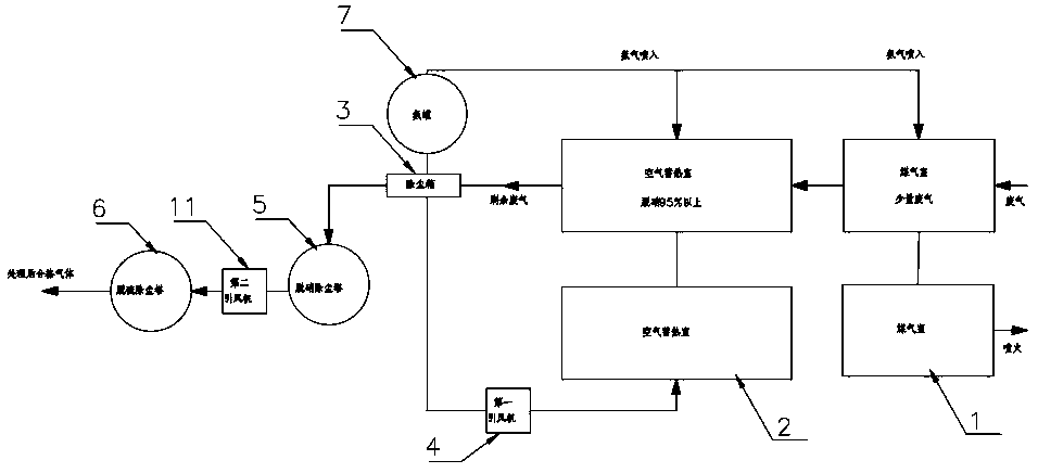
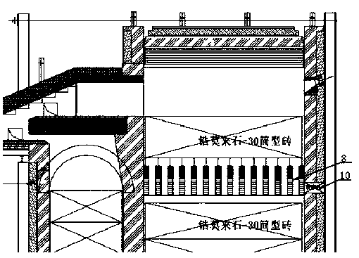
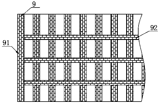
[0029] according to Figure 1-4 The shown method for denitrification of waste gas from a glass factory includes a gas chamber 1, an air heat storage chamber 2 is provided on one side of the gas chamber 1, and a dust removal box 3 is provided at the output end of the air heat storage chamber 2, and the dust removal box 3 and the air heat storage chamber 2 are provided with a return air pipe, the middle part of the air return pipe is provided with a first induced draft fan 4, the output end of the dust removal box 3 is provided with a denitrification dust removal tower 5, and the output end of the denitrification dust removal tower 5 is provided with There is a desulfurization and dust removal tower 6, a second induced draft fan 11 is arranged between the denitrification and dust removal tower 5 and the desulfurization and dust removal tower 6, an ammonia tank 7 is arranged outside the gas chamber 1 and the air heat storage chamber 2, and the gas chamber 1 and the air heat stora...

Embodiment 2

[0044] according to Figure 1-4 The shown method for denitrification of waste gas from a glass factory includes a gas chamber 1, an air heat storage chamber 2 is provided on one side of the gas chamber 1, and a dust removal box 3 is provided at the output end of the air heat storage chamber 2, and the dust removal box 3 and the air heat storage chamber 2 are provided with a return air pipe, the middle part of the air return pipe is provided with a first induced draft fan 4, the output end of the dust removal box 3 is provided with a denitrification dust removal tower 5, and the output end of the denitrification dust removal tower 5 is provided with There is a desulfurization and dust removal tower 6, a second induced draft fan 11 is arranged between the denitrification and dust removal tower 5 and the desulfurization and dust removal tower 6, an ammonia tank 7 is arranged outside the gas chamber 1 and the air heat storage chamber 2, and the gas chamber 1 and the air heat stora...

Embodiment 3

[0059] according to Figure 1-4 The shown method for denitrification of waste gas from a glass factory includes a gas chamber 1, an air heat storage chamber 2 is provided on one side of the gas chamber 1, and a dust removal box 3 is provided at the output end of the air heat storage chamber 2, and the dust removal box 3 and the air heat storage chamber 2 are provided with a return air pipe, the middle part of the air return pipe is provided with a first induced draft fan 4, the output end of the dust removal box 3 is provided with a denitrification dust removal tower 5, and the output end of the denitrification dust removal tower 5 is provided with There is a desulfurization and dust removal tower 6, a second induced draft fan 11 is arranged between the denitrification and dust removal tower 5 and the desulfurization and dust removal tower 6, an ammonia tank 7 is arranged outside the gas chamber 1 and the air heat storage chamber 2, and the gas chamber 1 and the air heat stora...


PUM


Abstract

The invention discloses a glass factory waste gas denitration method and belongs to the technical field of waste gas purification. A gas chamber is included. An air heat storage chamber is arranged onone side of the gas chamber, and a dust removing box is arranged at the output end of the air heat storage chamber. A gas return pipe is arranged between the dust removing box and the air heat storage chamber, a first induced draught fan is arranged at the middle portion of the gas return pipe, and a denitration dust removing tower is arranged at the output end of the dust removing box. By meansof the glass factory waste gas denitration method, a selective non-catalytic-reduction denitration method is adopted for conducting denitration on glass kiln waste gas, the treatment cost is reduced,great economic benefits and social benefits are achieved, ammonia gas and NOX are reacted to form N2 and H2O in the environment with the temperature being 850 DEG C to 1100 DEG C, the ammonia gas is sprayed evenly through a spray gun, the NOX can be reacted sufficiently in a mixed reaction space 8, in addition, the reaction speed is high, the denitration effect is good, and therefore the waste gasdischarged into the atmosphere reaches the environment-friendly requirement, the technology is simple, and use and popularization are facilitated.

Description

technical field [0001] The invention relates to the technical field of exhaust gas purification, and more specifically, the invention relates to a method for denitration of exhaust gas from a glass factory. Background technique [0002] Exhaust gases from glass factories contain some nitrogen oxides (NO X ), under the action of sunlight, it will cause photochemical reactions and form photochemical smog, thus causing serious air pollution. High levels of nitric acid rain, photochemical smog, ozone depletion, and other problems are all related to low levels of NO in the atmosphere X There are relationships. Nitrogen oxide pollution is an important environmental problem. With the development of economy and society, the control standards of nitrogen oxides will gradually become stricter. In order to further reduce the content of nitrogen oxides in the waste gas of the glass factory, it is necessary to carry out denitrification treatment on the waste gas produced by the glass ...

Claims


Application Information

Patent Timeline
IPC IPC(8): F23J15/00F23J15/02B01D53/56B01D53/75B01D53/76
CPCF23J15/00F23J15/003F23J15/02F23J15/022B01D53/56B01D53/75B01D53/76B01D2258/0241B01D2251/2062B01D2257/30Y02C20/10
Inventor 徐青山
Owner 山东郓城正华玻璃科技有限公司
Learn More