
Laser cladding repair method for lip crack of piston rod of aircraft 300M steel landing gear

A technology of laser cladding and repairing method, which is applied in the direction of metal material coating process, coating, etc., can solve the problems of small workpiece deformation, low reliability, and poor mechanical properties in the heat-affected zone, so as to solve crack faults and ensure Safe use requirements, high economic benefits

Inactive Publication Date: 2019-11-15
国营芜湖机械厂
View PDF8 Cites 10 Cited by
  • Summary
  • Abstract
  • Description
  • Claims
  • Application Information

AI Technical Summary

Problems solved by technology

[0003] Aiming at the problems of poor mechanical properties and low reliability of traditional argon arc welding repair, a landing gear is proposed by utilizing the characteristics of laser cladding technology, such as high dimensional accuracy, small heat-affected zone, very small workpiece deformation, uniform structure, and stable mechanical properties. Laser Cladding Repair Technology for Piston Rod Cracks
[0004] For example, the application number CN201710785371.9 is an electromagnetic stirring laser cladding repair method for ultra-high-strength steel landing gear components, including the following steps: (1) preparing laser cladding repair materials, (2) cleaning the surface before repairing, (3) electromagnetic stirring assistance Laser cladding repair, (4) mechanical processing, (5) non-destructive testing, (6) stress relief annealing to complete the repair, the patent did not conduct a simulation performance test on the landing gear before the repair, so the reliability of the process cannot be guaranteed

Method used


Image

  • Laser cladding repair method for lip crack of piston rod of aircraft 300M steel landing gear

Examples


Embodiment Construction

[0033] In order to enable those skilled in the art to better understand the technical solutions of the present invention, the present invention will be described more clearly and completely below in conjunction with the accompanying drawings in the embodiments. Of course, the described embodiments are only a part of the present invention. Not all, based on this embodiment, other embodiments obtained by those skilled in the art without creative efforts are all within the protection scope of the present invention.

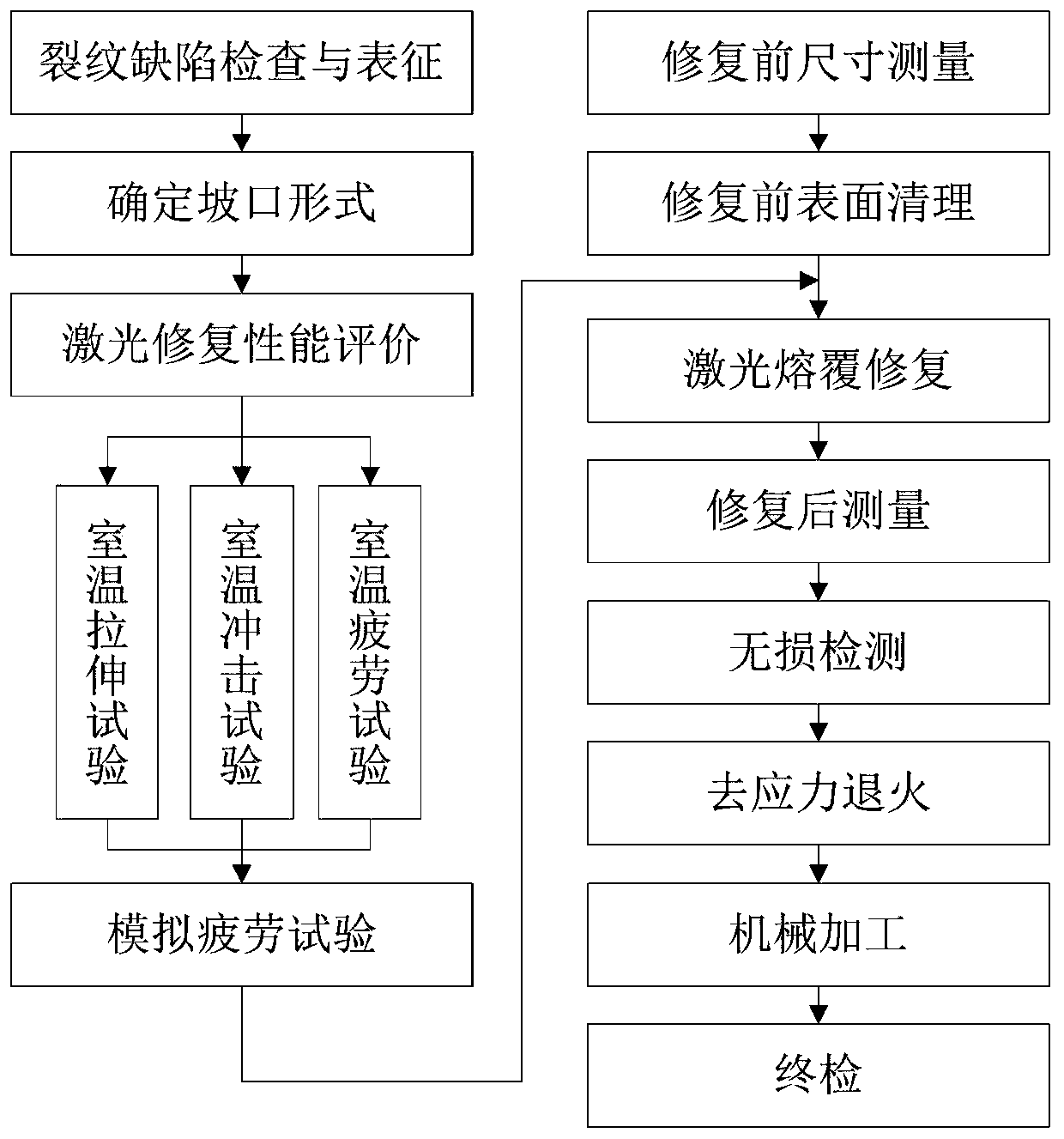
[0034] Such as figure 1 Shown, a kind of aircraft 300M steel landing gear piston rod lip crack laser cladding repair method, comprises the following steps:

[0035] The first step: Determine the laser repair process parameters by simulating the tensile, impact and fatigue performance experiments of the piston rod, and at the same time determine that the groove form of the laser cladding repair is V-shaped; before determining the laser repair process parameters, use v...


PUM

PropertyMeasurementUnit
tensile strengthaaaaaaaaaa

Abstract

The invention relates to a laser cladding repair method for a lip crack of a piston rod of an aircraft 300M steel landing gear. The method comprises the following steps of 1, determining laser repairprocess parameters by simulating stretching, impact and fatigue performance experiments of the piston rod, and meanwhile determining that the groove type of laser cladding repair is V-shaped; 2, selecting a simulation part before repairing, carrying out a simulation part fatigue experiment, evaluating an experiment result, and determining a final laser cladding repair process; 3, carrying out laser repair on the crack of the piston rod; 4, detecting a repair area of the piston rod to find no crack and non-fusion defect after the repair is completed; and 5, processing the repair area, recovering the size, and meeting the drawing or assembly requirements. According to the laser cladding repair method, the fatigue experiment is carried out on the simulation part of the piston rod to determinethe final repair process, it is guaranteed that the piston rod do not crack in the long period of use, so that the safety use requirements of an aircraft in the service life period can be ensured.

Description

technical field [0001] The invention relates to the field of piston rod repair, in particular to a laser cladding repair method for cracks on the piston rod lip of an aircraft 300M steel landing gear. Background technique [0002] Fatigue cracks are prone to occur in structural parts such as the outer cylinder of the aircraft landing gear, piston rod, body parts, joints and shafts. The traditional argon arc welding has a large thermal impact, is easy to deform, has a large residual stress, and has low repair reliability, which cannot meet the repair requirements. With the prolongation of the service life of the aircraft, the landing gear parts are subjected to long-term impact loads and are in a corrosive environment, and the probability of fatigue damage is increasing. In particular, the value of the landing gear piston rod is extremely high, and the scrapping of a single piece will lead to the scrapping of the entire landing gear device. The economic loss is huge. Carry o...

Claims


Application Information

Patent Timeline
Patent Type & Authority Applications(China)
IPC IPC(8): C23C24/10
CPCC23C24/10
Inventor 南健曹强孙兵兵姚念奎张志强唐斌程庆元代雪婷
Owner 国营芜湖机械厂
Learn More