A mram memory chip using fully depleted silicon-insulator fd-soi field effect transistor
A technology of FD-SOI and memory chips, which is applied in the direction of information storage, static memory, digital memory information, etc., can solve the problems of field effect tubes not working properly, burning out, etc., and achieve the effect of solving insufficient driving current and eliminating latch-up effect
- Summary
- Abstract
- Description
- Claims
- Application Information
AI Technical Summary
Problems solved by technology
Method used
Image
Examples
Embodiment 1
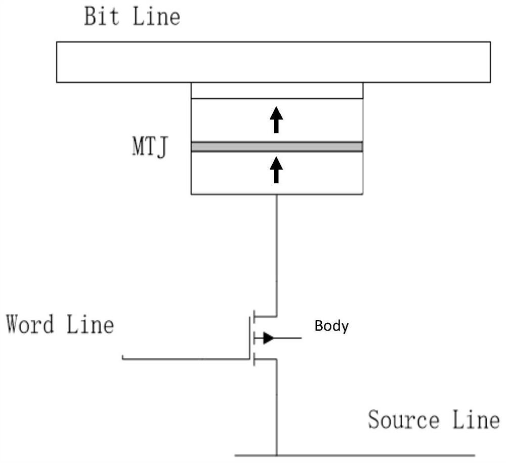
[0036] An MRAM memory chip using a fully depleted silicon-on-insulator FD-SOI field effect transistor, the field effect transistor of each MRAM memory unit of the MRAM memory chip adopts a fully depleted silicon-on-insulator FD-SOI field effect transistor, such as Figure 5 shown. The MRAM chip also includes a body potential control unit, which regulates the body potential of the back gate of the memory chip.
[0037] Since the back gate body of the fully depleted silicon-on-insulator FD-SOI field effect transistor is isolated by a layer of silicon oxide dielectric layer between the source source and the drain drain, the MRAM chip raises the back gate When the body potential is used, PNP and NPN type triode structures will not be formed, and there will be no latch-up effect, which will not bring area and cost costs.
Embodiment 2
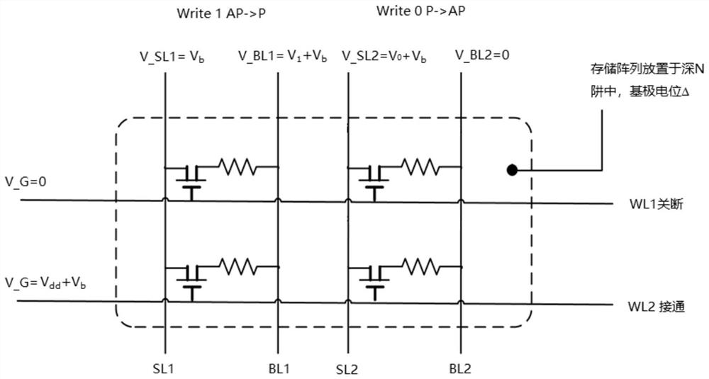
[0039] A design method for adjusting the body potential of the back gate of an MRAM memory chip using a fully depleted silicon-on-insulator FD-SOI field effect transistor, such as Image 6 and Figure 7 As shown, the specific design method is as follows:
[0040] The back gate body potential is set to V_body=V b , V bThe value can be flexibly set according to design needs. Preferably, the body potential of the back gate can be reasonably adjusted under different operations through the back gate body potential control circuit.
[0041] During a read operation, take V b =0.
[0042] The specific method for adjusting the body potential of the back gate of the MRAM memory chip is as follows:
[0043] When writing 0 direction:
[0044] The source line potential V_SL is set to V 0 +V b , the bit line potential V_BL is set to 0, and the gate (word line) potential V_G is set to V dd +V b . Among them, V 0 +V b is the voltage signal that the read drive circuit needs to ge...
PUM
 Abstract
Description
Claims
Application Information
 - R&D
- Intellectual Property
- Life Sciences
- Materials
- Tech Scout
- Unparalleled Data Quality
- Higher Quality Content
- 60% Fewer Hallucinations
Browse by: Latest US Patents, China's latest patents, Technical Efficacy Thesaurus, Application Domain, Technology Topic, Popular Technical Reports.
© 2025 PatSnap. All rights reserved.Legal|Privacy policy|Modern Slavery Act Transparency Statement|Sitemap|About US| Contact US: help@patsnap.com


