
Liquid-liquid-solid three-phase separation device for waste oil

A technology for three-phase separation and industrial waste oil, which is applied in the directions of liquid separation, electric liquid separation, and cyclone axial reversal devices, etc. The problem of reducing the inlet flow of the device and affecting the separation effect can shorten the demulsification and desolidification time, improve the application prospect, and reduce the energy consumption of oil purification.

Pending Publication Date: 2019-06-21
CHONGQING TECH & BUSINESS UNIV
View PDF2 Cites 3 Cited by
  • Summary
  • Abstract
  • Description
  • Claims
  • Application Information

AI Technical Summary

Problems solved by technology

At present, the removal of solid particles is mainly based on filtration. However, if the filter is used for too long, the filter screen will be blocked, resulting in a decrease in the inlet flow of the separation device and affecting the separation effect.
For waste oil emulsions with complex components, it is difficult to achieve efficient and economical dehydration purification and solid removal treatment with a single process method or method

Method used


Image

  • Liquid-liquid-solid three-phase separation device for waste oil
  • Liquid-liquid-solid three-phase separation device for waste oil
  • Liquid-liquid-solid three-phase separation device for waste oil

Examples


Embodiment Construction

[0023] The present invention will be further described below in conjunction with the accompanying drawings and specific embodiments, so that those skilled in the art can better understand the present invention and implement it, but the examples given are not intended to limit the present invention.

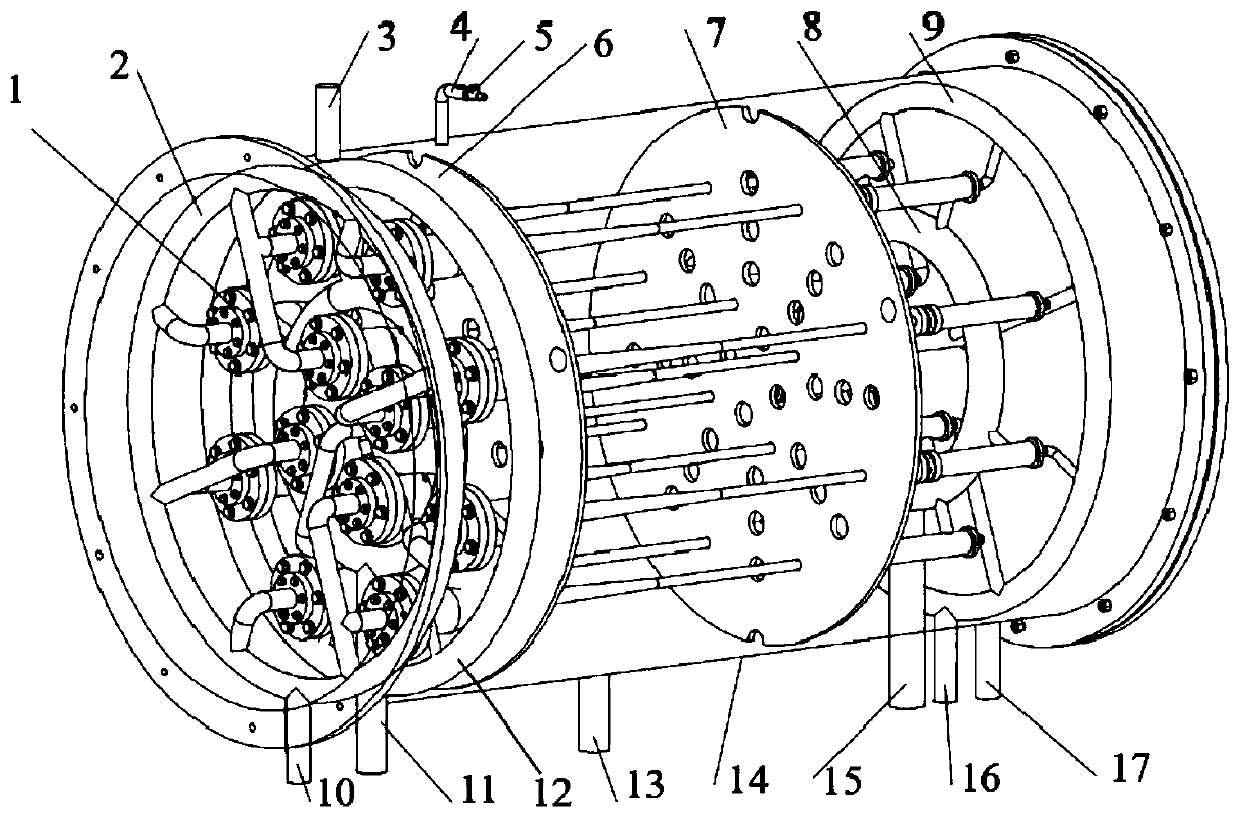
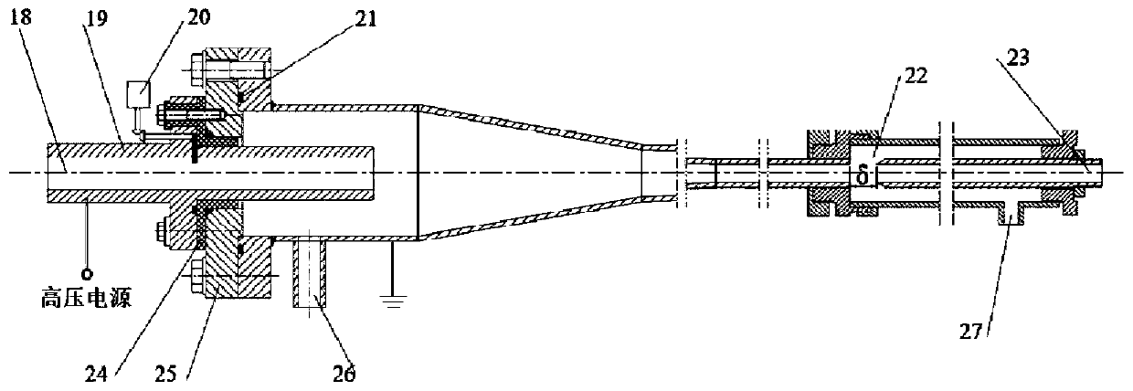
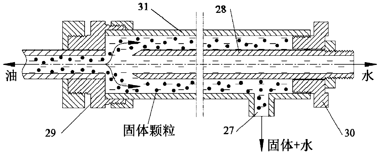
[0024] As shown in the figure, a waste oil liquid-liquid-solid three-phase separation device provided in this embodiment includes an oil bath heating tank, a cyclone separation unit and a solid removal unit; the oil bath heating tank is provided with several cyclones A flow separation unit, the cyclone separation unit is fixed on the tank body of the oil bath heating tank through two bracket steel plates; the cyclone separation unit is provided with an underflow tube, and the bottom flow port of the underflow tube is provided with a solid removal unit, The underflow pipe and the solid removal unit are connected by threads.

[0025] The solid removal unit includes a first connector...


PUM


Abstract

The invention discloses a liquid-liquid-solid three-phase separation device for industrial waste oil. The liquid-liquid-solid three-phase separation device comprises an oil bath heating tank, swirlingseparation units and solid removing units, wherein a plurality of swirling separation units are arranged inside the oil bath heating tank; the swirling separation units are fixed into the oil bath heating tank; the solid removing units are connected with bottom flowing pipes of the swirling separation units; the solid removing units are used for separating solid particles from liquid inflowing from the bottom flowing pipes; solid removing outer pipes are arranged at the bottom flowing ends of the swirling separation units; second connecting components are arranged at the tail ends of the solid removing outer pipes; solid removing inner pipes are arranged at bottom flowing ports of the bottom flowing pipes to form solid removing gaps. According to the liquid-liquid-solid three-phase separation device provided by the invention, in allusion to the characteristics of an industrial waste oil emulsion, the defects of the conventional separation process are overcome, and emulsion droplets are rapidly gathered and enlarged under the action of an electric field; liquid-liquid-solid three-phase separation is achieved; liquid-liquid-solid three-phase separation device not only can achieve demulsification and dehydration treatment of the industrial waste oil emulsion, but also can achieve the separation of solid particles, and has a very good application prospect, a good economic value and good social benefits.

Description

technical field [0001] The invention relates to the technical field of waste oil treatment, in particular to a liquid-liquid-solid three-phase separation device for waste oil. Background technique [0002] As the blood of industry, lubricating oil is widely used in the fields of machinery, electric power, transportation and chemical industry, and it is easy to form industrial waste oil during storage, transportation, filling and use. Industrial waste oil contains a lot of impurities, including: solid particle impurities, colloid and water, which aggravates the corrosion and wear of equipment. Today, when oil resources are so scarce, the recycling of industrial waste oil has extremely important practical significance for environmental protection and national strategies. Among the numerous industrial waste oil recycling processes, the first step is to dehydrate, purify and remove solids. At present, the removal of solid particles is mainly based on filtration. However, if th...

Claims


Application Information

Patent Timeline
Patent Type & Authority Applications(China)
IPC IPC(8): C10G53/02C10G33/02C10G31/10
CPCB01D17/0217B01D17/042B01D17/06B01D21/245B01D21/267B01D21/30B04C5/13B04C5/14B04C5/16B04C5/20B04C5/28B04C9/00B04C2005/133B04C2009/001B01D17/0214B04C5/103
Inventor 龚海峰张贤明李文龙彭烨
Owner CHONGQING TECH & BUSINESS UNIV
Learn More