Sintered compact for forming rare earth sintered magnet, and method for manufacturing same

A technology of sintered magnets and manufacturing methods, applied in the direction of inductance/transformer/magnet manufacturing, magnetic objects, manufacturing motor generators, etc., can solve the problems of uneven and uneven magnet structure, and achieve the effect of suppressing shortcomings

Active Publication Date: 2019-05-21
NITTO DENKO CORP
View PDF12 Cites 7 Cited by
  • Summary
  • Abstract
  • Description
  • Claims
  • Application Information

AI Technical Summary

Problems solved by technology

[0016] The invention of the present application was made to solve such problems in the prior art. Its purpose is to employ pressure sintering in order to suppress uneven shrinkage that occurs during sintering, and to suppress the disadvantage of pressure sintering, that is, To provide a method for producing a rare earth sintered magnet that provides a rare earth sintered magnet of a desired shape having magnetic properties equal to or higher than those obtained by vacuum sintering due to unevenness in the structure of the magnet due to pressurization and using The manufacturing method of the sintered body of the manufacturing method further provides a rare earth sintered magnet and a sintered body having predetermined characteristics

Method used


Image

  • Sintered compact for forming rare earth sintered magnet, and method for manufacturing same
  • Sintered compact for forming rare earth sintered magnet, and method for manufacturing same
  • Sintered compact for forming rare earth sintered magnet, and method for manufacturing same

Examples


Embodiment 1

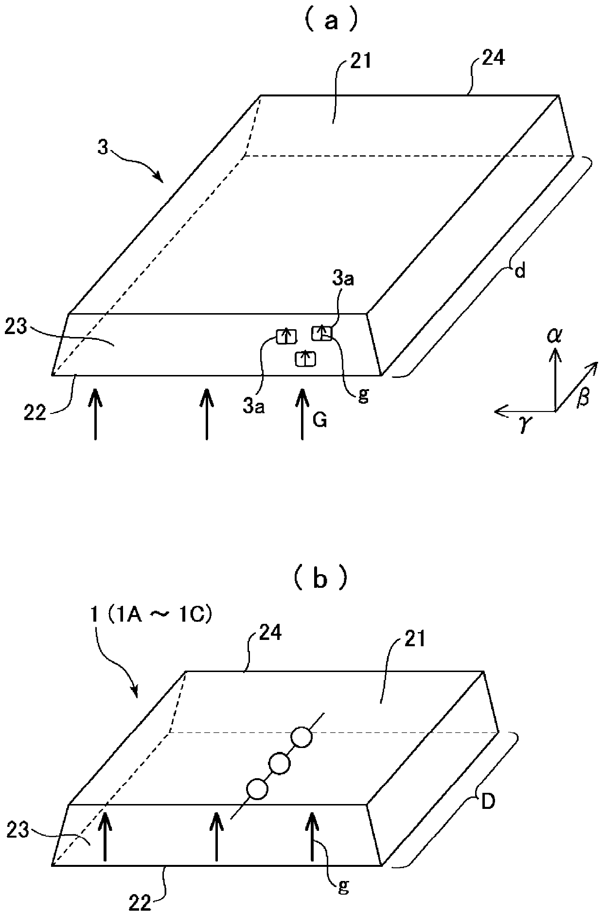
[0171] use Figure 9 A sintered body was produced in the following procedure for the trapezoidal processing sheet shown. No deoiling treatment was performed.

[0172]

[0173] The alloy obtained by the strip casting method was allowed to occlude hydrogen at room temperature and kept at 0.85 MPa for 1 day. Then, hydrogen fragmentation was carried out by maintaining at 0.2 MPa for 1 day while cooling with liquid Ar. The composition of the alloy is "comprising Nd: 25.25wt%, Pr: 6.75wt%, B: 1.01wt%, Ga: 0.13wt%, Nb: 0.2wt%, Co: 2.0wt%, Cu: 0.13wt%, the rest Fe, Al: 0.10wt%, and other unavoidable impurities".

[0174]

[0175] Fine pulverization was carried out by jet mill pulverization as follows. 1 part by weight of methyl hexanoate was mixed with 100 parts by weight of the coarse alloy powder subjected to hydrogen pulverization, and then pulverized by a helium jet mill pulverizer (device name: PJM-80HE, manufactured by NPK). The collection of pulverized alloy particles ...

Embodiment 2~9、 comparative example 1~5

[0193] Except having changed to the conditions described in Table 1, the same operation as Example 1 was performed, and each sintered body was obtained.

[0194] From Examples 2 to 9, it is clear that the high-temperature heat treatment "B" at 970°C for 2 to 11 hours after pressure sintering exhibits a coercive force Hcj of 16.4 [kOe] or more, and the squareness Hk / Hcj It is also shown as 90% or more.

[0195] On the other hand, as shown in Comparative Examples 1 and 4, when the high-temperature heat treatment "B" is not performed, although the squareness Hk / Hcj exceeds 90%, the coercive force Hcj can only be obtained at about 12 [kOe] very low value.

[0196] In addition, as shown in Comparative Examples 2 and 3, when the temperature of the high-temperature heat treatment "B" was as low as 700°C or 900°C, the temperature was lower than that in the case of not performing the high-temperature heat treatment "B" shown in Comparative Examples 1 and 4. Compared with that, almost...

Embodiment 10~17、 comparative example 6、7

[0199] The same evaluation and analysis as in Table 1 were performed for the sintered body produced under the conditions in Table 1 or the rare earth sintered magnet obtained by magnetizing the same. The results are shown in Table 2. In addition, the conditions other than the conditions especially described in Table 2 were made into the same conditions as Example 1.

[0200]

[0201] In Table 2, the alloy composition "A" refers to the alloy composition used in Example 1, on the other hand, the alloy composition "B" refers to "containing Nd: 22.25wt%, Dy: 3.00wt%, Pr: 6.75wt% %, B: 1.01wt%, Ga: 0.13wt%, Nb: 0.2wt%, Co: 2.0wt%, Cu: 0.13wt%, the remainder is Fe, Al: 0.10wt%, and other unavoidable impurities" .

[0202] In Table 2, by setting the feed rate of the raw material during pulverization to 4.3 kg / h, the pulverized particle size of the fine pulverization which is the basis of the rare earth magnet forming material is set to about 3 μm.

[0203] In addition, in the d...


PUM

PropertyMeasurementUnit
particle diameteraaaaaaaaaa
particle sizeaaaaaaaaaa

Abstract

Provided is a method of manufacturing a sintered compact for forming a rare earth sintered magnet of a desired shape with high magnetic properties by suppressing variations in magnetic structure caused by pressurization, which is a disadvantage of pressure sintering. Further provided is a rare earth sintered magnet and the like having prescribed properties. A material for forming a rare earth magnet containing magnet material particles is filled into a mold in a state in which the easy axis of magnetization is oriented in a single plane. While a pressurizing force of a prescribed magnitude isexerted on the material for forming the rare earth magnet that has been filled into the mold, the material for forming the rare earth magnet is sintered by being heated to a sintering temperature, thereby forming a sintered compact in which the magnet material particles are integrally sintered. Thereafter, while a pressure lower than that of the pressurizing force during sintering is applied to the sintered compact, a high temperature heat treatment is performed within a maximum temperature range of greater than 900 DEG C and lower than or equal to 1100 DEG C, with the difference between thismaximum temperature and the maximum temperature during pressure sintering being 250 DEG C or lower.

Description

technical field [0001] The present invention relates to a method for producing a sintered body for forming a rare earth sintered magnet, and particularly to a method for producing a sintered body for forming a rare earth sintered magnet including magnet material particles having an easy axis of magnetization by pressure sintering, and a sintered body formed by the method. A sintered body for forming a rare earth sintered magnet. The present invention also relates to a rare earth sintered magnet obtained by magnetizing a sintered body for forming a rare earth sintered magnet. Background technique [0002] Rare-earth permanent magnets are attracting attention as magnets used in rotating equipment such as motors of various electric and electronic equipment. Rare earth permanent magnets are generally produced through a sintering process of sintering solid magnet powder molded into a desired shape at high temperature in a sintering mold. Through the sintering process, magnetic ...

Claims


Application Information

Patent Timeline
Patent Type & Authority Applications(China)
IPC IPC(8): H01F41/02B22F1/00B22F3/00B22F3/10B22F3/14B22F3/24C21D6/00H01F1/057H02K15/03C22C38/00B22F1/10B22F1/17
CPCH01F1/057H01F41/02B22F3/14B22F1/00B22F3/00B22F3/10B22F3/24C21D6/00B22F1/10H02K15/03B22F3/16B22F3/15B22F2304/10B22F2003/248C22C38/005C22C38/002C22C38/16C22C2202/02H01F1/0577H01F41/0273C22C38/12C22C38/10H01F1/0054B22F3/12C22C38/00H01F1/0576H01F41/0266B22F3/02H01F41/0293
Inventor 藤川宪一尾关出光山本贵士江部宏史信田拓哉
Owner NITTO DENKO CORP
Why Eureka
Try Eureka