
Coating device

A coating device and coating technology, applied in the direction of the surface coating liquid device, display device, spraying device, etc., can solve the problems of nozzle 202 skew, interval deviation, uneven coating, etc., to prevent deviation and suppress Effect of uneven coating and preventing skew

Inactive Publication Date: 2006-10-11
HOYA CORP
View PDF1 Cites 2 Cited by
  • Summary
  • Abstract
  • Description
  • Claims
  • Application Information

AI Technical Summary

Problems solved by technology

[0009] In this way, the nozzle 202 is fixed to the pedestal 206 using the mounting screw 207, and is mounted on the nozzle support shaft 204, so that the nozzle 202 is skewed by the tightening force of the mounting screw 207.
Therefore, the gap formed in the capillary gap 203 of the nozzle 202 is deviated due to the above-mentioned skew, and the problem of uneven coating may occur.
[0010] Moreover, since the nozzle 202 is fastened and fixed on the pedestal 206 with the mounting screw 207 for a long time, the skew generated at each fastening position is accumulated, and at this time, there is also a deviation in the interval of the capillary gap 203 of the nozzle 202. There may be problems with uneven coating

Method used


Image

  • Coating device
  • Coating device
  • Coating device

Examples


Embodiment Construction

[0030] Hereinafter, preferred embodiments of the present invention will be described with reference to the drawings.

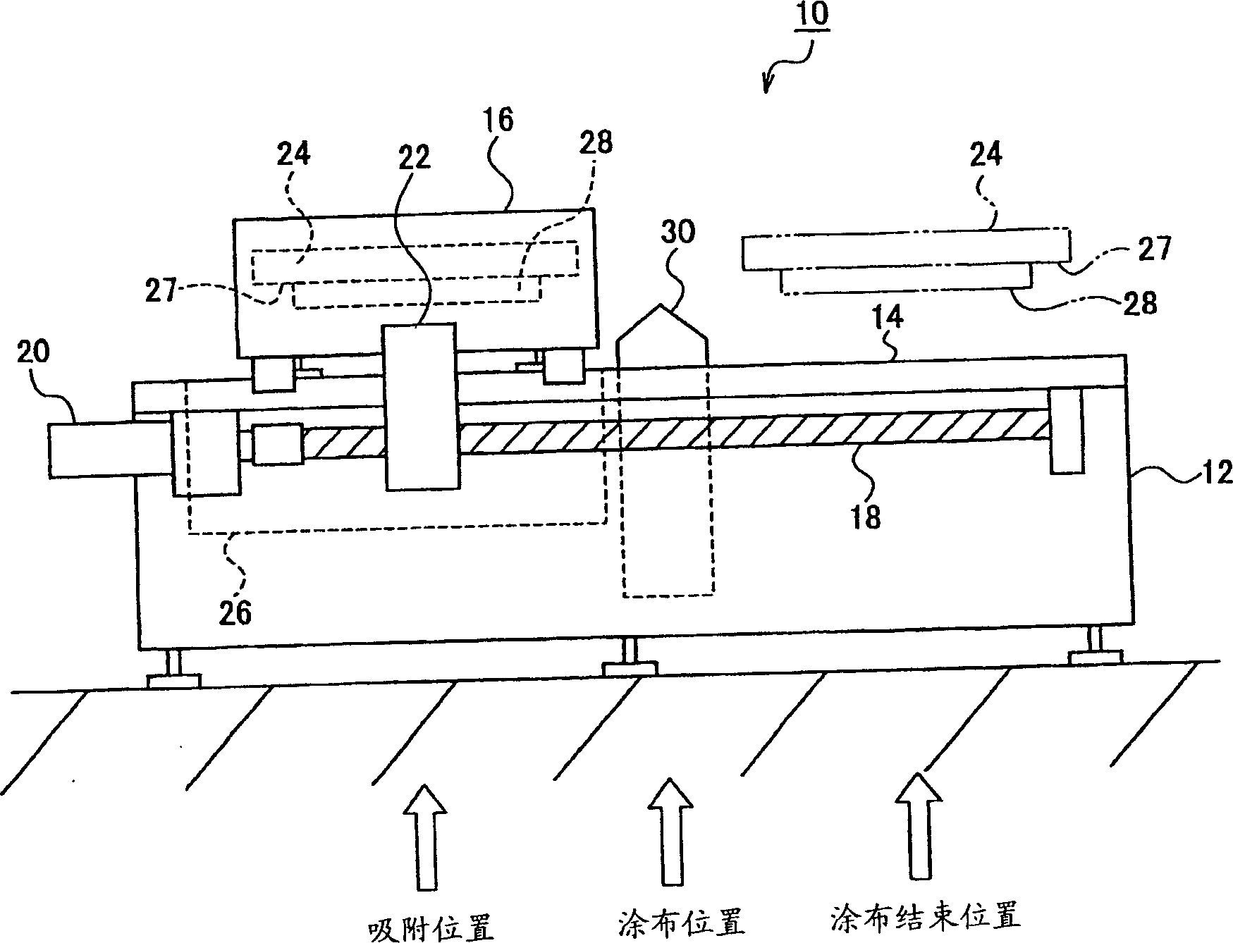
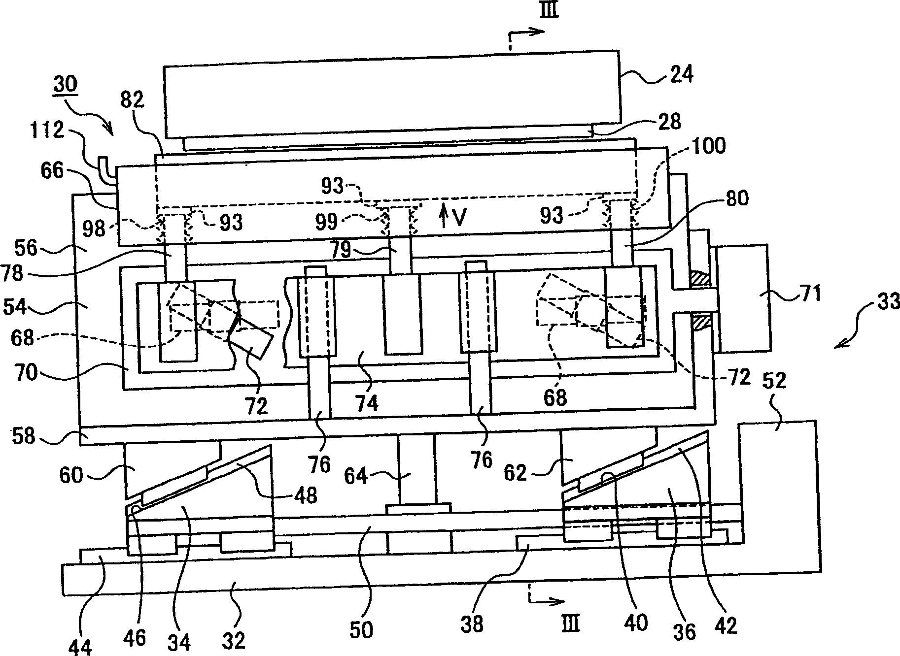
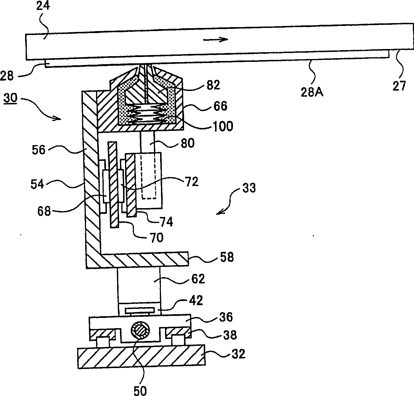
[0031] figure 1 It is a schematic side view showing one embodiment of the coating apparatus of the present invention. figure 2 yes means figure 1 Front view of the coating system. image 3 is along figure 2 Sectional view of line III-III.

[0032] Such as figure 1 As shown, the coating device 10 is composed of: a base frame 12; a coating system 30 arranged on the base frame 12; a moving frame 16, which is supported on the base frame 12 and can move horizontally; a suction table (hereinafter referred to as stage) 24, which is installed on the moving frame 16, and adsorbs the substrate 28; and a holding system 26, which holds the substrate 28 in a detachable manner.

[0033] The substrate 28 is a photomask in which a light-shielding film is formed on a transparent substrate. The coating liquid applied to the substrate 28 is a resist, and forms a ligh...


PUM


Abstract

The present invention provides a coating device capable of suppressing uneven coating of the coating liquid when the coating liquid is coated on a surface to be coated with a nozzle. The coating device includes: a nozzle having a capillary gap communicated with the top opening and allowing the coating liquid to guide the top opening through the capillary gap; The cloth surface is approached or separated, and the coating liquid that has reached the above-mentioned tip opening can be in liquid contact with the surface to be coated; The coating liquid in the above-mentioned tip opening can be coated on the surface to be coated. The lifting mechanism part has a nozzle support shaft for supporting the nozzle, a pedestal is fixed on the top end of the nozzle support shaft, and a coil is wound around the nozzle support shaft, and the nozzle is held by the magnetic force of the electromagnet generated by energizing the coil. Mounted on the pedestal above.

Description

technical field [0001] The present invention relates to a coating device for coating a coating liquid with a substrate to be coated facing downward. Background technique [0002] Conventionally, as a coating device for coating a coating liquid such as a photoresist on a substrate such as a silicon wafer, a spin coater is used, which drops the coating liquid on the center of the substrate, and then The substrate is rotated at high speed, so that the coating liquid is stretched by centrifugal force, and a coating film is formed on the surface of the substrate. [0003] However, the above-mentioned spin coater sometimes produces swelling called resist stripes on the peripheral edge of the substrate. Especially in a liquid crystal display device or a photomask for liquid crystal display device manufacture, it is necessary to apply a resist to a large substrate (for example, a substrate with a single side dimension of 300 mm or more), and the occurrence of streaks is remarkable....

Claims


Application Information

Patent Timeline
IPC IPC(8): B05C5/02B05B13/02B05D7/00
CPCG09F15/0012G09F15/0018G09F15/0025G09F15/0056G09F15/0068
Inventor 石崎高広
Owner HOYA CORP
Learn More