
Cooling assembly of magnetron sputtering reaction chamber and magnetron sputtering equipment thereof

A technology for cooling components and reaction chambers, applied in sputtering plating, ion implantation plating, metal material coating process, etc., can solve problems such as substandard film stress, affecting film quality, limited cooling capacity, etc., and achieve reduction Difficulty in disassembly, improvement of product quality, and effect of reducing temperature rise

Pending Publication Date: 2019-05-10
BEIJING NAURA MICROELECTRONICS EQUIP CO LTD
View PDF5 Cites 4 Cited by
  • Summary
  • Abstract
  • Description
  • Claims
  • Application Information

AI Technical Summary

Problems solved by technology

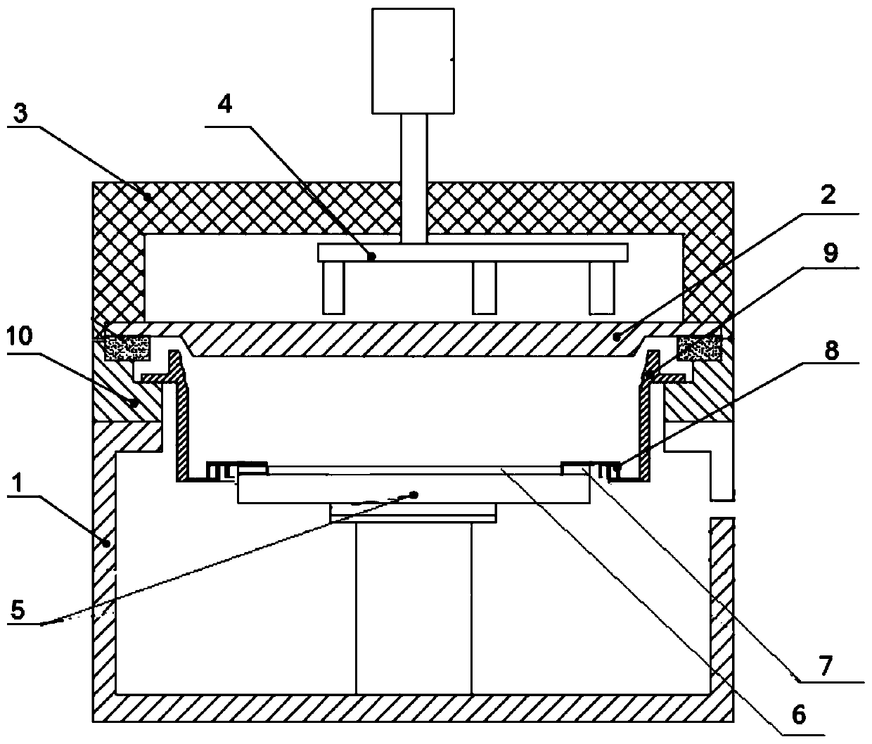
[0003] When the energy of the plasma is high enough and bombards the target 2 under the action of the magnetic field formed by the rotating magnetron 4, metal atoms or metal ions will escape from the surface of the target and be deposited on the wafer 6 by diffusion. 5 is the pedestal for carrying the substrate 6, but even with the binding effect of the magnetron 4 on the metal atoms, there are still a large amount of metal atoms and metal ions that will deposit on the inner wall of the reaction chamber 1, and pollute the substrate and the reaction chamber after falling off. Chamber 1, in view of the fact that the reaction chamber is not easy to clean, a lining (Shield) 9, a cover plate (Cover ring) 8, and a deposition ring (Dep-ring) 7 are set up to shield the metal atoms and metal ions that pollute the reaction chamber , by increasing the surface roughness, the metal film of the lining (Shield) 9, cover plate (Cover ring) 8, and deposition ring (Dep-ring) 7 will not fall off, and regular cleaning, sandblasting, and spraying are required, and adapters are used The adapter 10 fixes the lining (Shield) 9, cover plate (Cover ring) 8, and deposition ring (Dep-ring) 7 on the reaction chamber 1. During the magnetron sputtering process, the escaped metal ions and atoms carry huge Heat will increase the temperature of the inner wall of the reaction chamber 1, especially the temperature rise of the lining (Shield) 9, cover plate (Cover ring) 8, and deposition ring (Dep-ring) 7 exceeds the temperature range of the process reaction , is not conducive to the progress of the process, and a series of problems such as film stress not up to standard and whisker defects have appeared
At present, although various methods are used to cool down the inner lining 9, etc., there are problems such as limited cooling capacity, slow thermal conductivity, low efficiency, high cost, and difficult processing, which affect the quality of the film.

Method used


Image

  • Cooling assembly of magnetron sputtering reaction chamber and magnetron sputtering equipment thereof
  • Cooling assembly of magnetron sputtering reaction chamber and magnetron sputtering equipment thereof
  • Cooling assembly of magnetron sputtering reaction chamber and magnetron sputtering equipment thereof

Examples


Embodiment Construction

[0023] The present invention will be described more fully hereinafter with reference to the accompanying drawings, in which exemplary embodiments of the invention are illustrated. The following will clearly and completely describe the technical solutions in the embodiments of the present invention with reference to the accompanying drawings in the embodiments of the present invention. Obviously, the described embodiments are only some, not all, embodiments of the present invention. Based on the embodiments of the present invention, all other embodiments obtained by persons of ordinary skill in the art without making creative efforts belong to the protection scope of the present invention. The technical solution of the present invention will be described in various aspects in conjunction with the figures and embodiments below.

[0024] For the convenience of description below, the "left", "right", "upper" and "lower" referred to below are consistent with the left, right, upper ...


PUM


Abstract

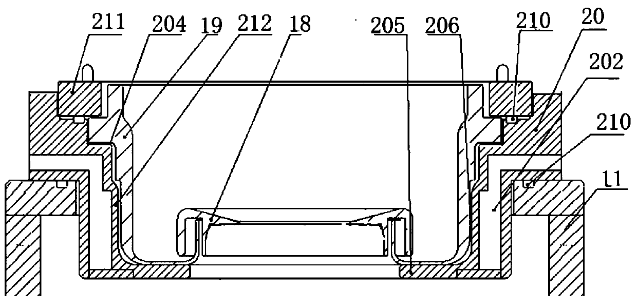
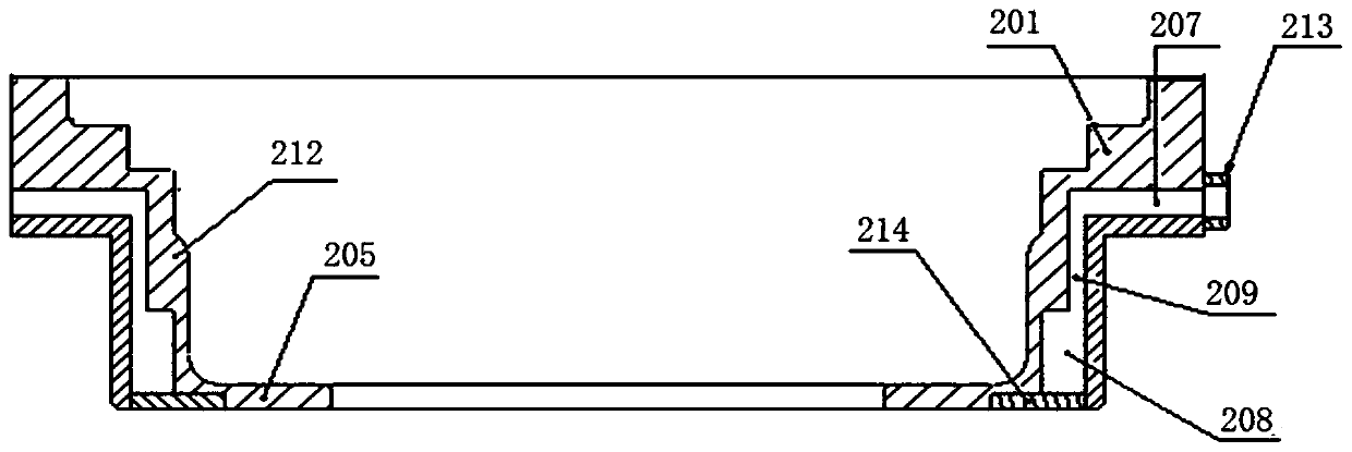
The embodiment of the invention discloses a cooling assembly of a magnetron sputtering reaction chamber and magnetron sputtering equipment thereof. The assembly comprises an adapter, wherein the adapter is provided with a bottom part and a side wall for shielding a liner and is used for fixing the liner into the reaction chamber; a preset gap is arranged between the side wall of the adapter and aside wall of the liner; the bottom part of the adapter contacts a bottom part of the liner; and the adapter is provided with a cooling water channel for cooling the side wall and the bottom part of the liner. According to the cooling assembly and the magnetron sputtering equipment thereof provided by the invention, a heat contact area can be increased, so that the heat transfer efficiency of the side walls of the adapter and the liner is improved; through cooling the side wall and a bottom surface of the liner, the process reaction area temperature is stabilized, so that the influence of the reaction area temperature rise on a substrate and a thin film is avoided; through reducing a water channel processing step and the difficulty, the cleaning difficulty is reduced; and the water channelcan be sealed without the need of a seal ring, so that the risk of water leakage can be reduced.

Description

technical field [0001] The invention relates to the technical field of semiconductor manufacturing, in particular to a cooling assembly of a magnetron sputtering reaction chamber and a magnetron sputtering device thereof. Background technique [0002] Physical vapor deposition (Physical Vapor Deposition, PVD) technology is widely used in the semiconductor field. It uses sputtering (Sputtering) deposition technology to pass inert gases such as argon between the substrate and the target, and high voltage to ionize the inert gas. Plasma is generated, and the ability of bound electrons is enhanced by a magnetic field to make the generated plasma bombard the target, and atoms or ions of the target material are deposited on the substrate to form a thin film. Existing magnetron sputtering equipment such as figure 1 As shown, the equipment has a reaction chamber 1, the reaction chamber 1 has a built-in target 2, and an insulating material 3 is placed above the target 2 to realize t...

Claims


Application Information

Patent Timeline
Patent Type & Authority Applications(China)
IPC IPC(8): C23C14/35C23C14/54
Inventor 常青李冰边国栋
Owner BEIJING NAURA MICROELECTRONICS EQUIP CO LTD
Learn More