
A Fast Load Response LDO Based on Dual Power Rails

A dual power supply and power supply voltage technology, applied in the direction of adjusting electrical variables, instruments, control/regulation systems, etc., can solve the problems that affect the response speed of LDO, reduce the undershoot, and accelerate the response speed of the output terminal, so as to speed up the loop response The effects of speed, high stability, and fast load response

Active Publication Date: 2020-07-31
UNIV OF ELECTRONICS SCI & TECH OF CHINA
View PDF5 Cites 0 Cited by
  • Summary
  • Abstract
  • Description
  • Claims
  • Application Information

AI Technical Summary

Problems solved by technology

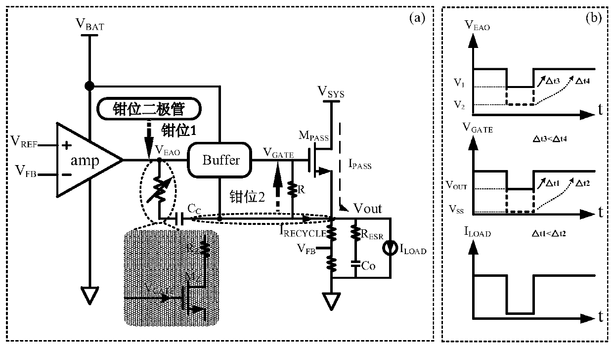
[0003] For the traditional LDO, when the load has a short light load duration and a heavy load-light load-heavy load jump, when the light load jumps and the heavy load power tube needs to change from V GS The state of <0 starts to respond, which affects the response speed of the LDO. The present invention proposes a fast load response LDO based on dual power supply rails, which improves the structure of the traditional LDO. By appropriately sacrificing the NMOS LDO loop part to the output voltage The response speed when overshoot occurs, thereby accelerating the response speed when undershoot occurs at the output end, so that the LDO proposed by the present invention can adjust the output in time when the load has a short-to-light-load jump of heavy load-light load-heavy load voltage, which can greatly reduce the undershoot compared with traditional LDO

Method used


Image

  • A Fast Load Response LDO Based on Dual Power Rails
  • A Fast Load Response LDO Based on Dual Power Rails
  • A Fast Load Response LDO Based on Dual Power Rails

Examples


Embodiment Construction

[0037] For NMOS LDO, the overshoot of the output voltage will be directly affected by the power transistor M PASS Gate-to-source voltage V GS This process is far ahead of the response of the loop, so the present invention speeds up the response speed of the loop when the output voltage undershoots by properly sacrificing the response speed of the loop when the output voltage overshoots. According to this idea, the LDO can The feedback loop is clamped when the output voltage is in an overshoot condition.

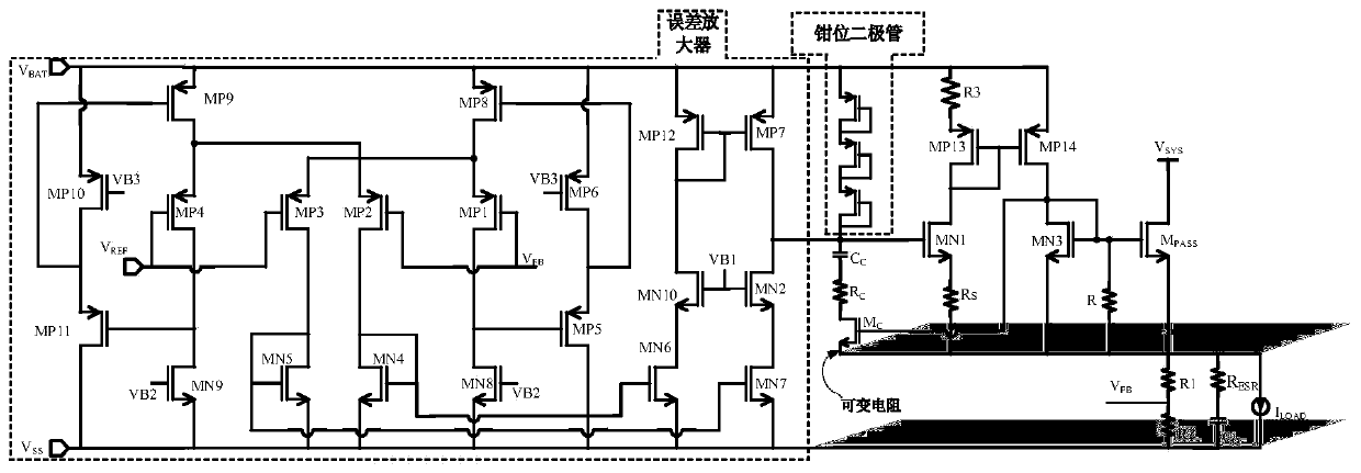
[0038] Such as figure 2 (a) is a topological schematic diagram of a fast load response LDO based on dual power rail power supply proposed by the present invention, including an error amplifier, an output unit, a buffer unit Buffer, a clamp unit and a compensation unit, and the output unit includes a power Tube MPASS , the first voltage dividing resistor R1 and the second voltage dividing resistor R2, the power tube M PASS NMOS tube, power tube M PASS The drain of the sec...


PUM


Abstract

The invention relates to a fast load response LDO based on dual power rail power supply, which belongs to the technical field of power management. It includes an error amplifier, an output unit, a buffer unit, a clamp unit and a compensation unit. The drain of the power transistor in the output unit is connected to the second-stage power supply voltage, and its source outputs the output voltage of the LDO and passes through the first voltage dividing resistor and the second The series structure of the voltage dividing resistors is connected to the ground potential; the inverting input terminal of the error amplifier is connected to the feedback voltage, its non-inverting input terminal is connected to the reference voltage, its power supply terminal is connected to the first stage power supply voltage, and its ground terminal is connected to the ground potential; the buffer unit is connected to Between the output terminal of the error amplifier and the gate of the power tube, and the output voltage of the LDO is used as the reference ground; the clamping diode is used to clamp the output voltage of the error amplifier; the compensation unit is used to provide the pole and dynamic zero point of the output terminal of the error amplifier. The invention speeds up the response speed of the loop when undershooting by clamping the output voltage of the error amplifier and the grid terminal voltage of the power tube when overshooting, and has high stability.

Description

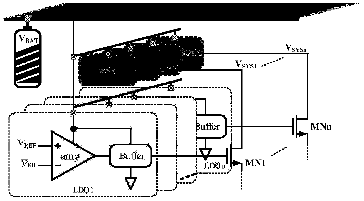
technical field [0001] The invention belongs to the technical field of power supply management, and in particular relates to a low-voltage linear regulator (LDO) circuit design with fast load response based on dual power supply rails. Background technique [0002] In portable mobile devices, the power management chip needs multiple buck circuits to output different voltages, and then drive each load point after being regulated by the LDO circuit. The LDO in this application can directly drive the control loop from the battery voltage with a higher voltage, and the output of the buck circuit provides current for the power tube, and then NMOS LDO can be designed without the need for a charge pump, such as figure 1 shown. In the case of some rapid load jumps, such as the flash memory of a smartphone, it is required that the LDO powering it can quickly make a corresponding stable supply voltage. For the traditional NMOS LDO, when the load jumps from heavy load to light load to...

Claims


Application Information

Patent Timeline
Patent Type & Authority Patents(China)
IPC IPC(8): G05F1/56
CPCG05F1/56
Inventor 明鑫张杰梁华王卓张波
Owner UNIV OF ELECTRONICS SCI & TECH OF CHINA
Learn More