Metal surface thin liquid film forming, controlling and measuring equipment
A technology of metal surface and measuring equipment, which is applied in the direction of measuring devices, instruments, scientific instruments, etc., can solve the problems that are not conducive to the corrosion test of metal thin liquid film, and the thickness of thin liquid film cannot be controlled, so as to achieve stable thickness, accurate thickness and convenient The effect of the operation
- Summary
- Abstract
- Description
- Claims
- Application Information
AI Technical Summary
Problems solved by technology
Method used
Image
Examples
Embodiment 1
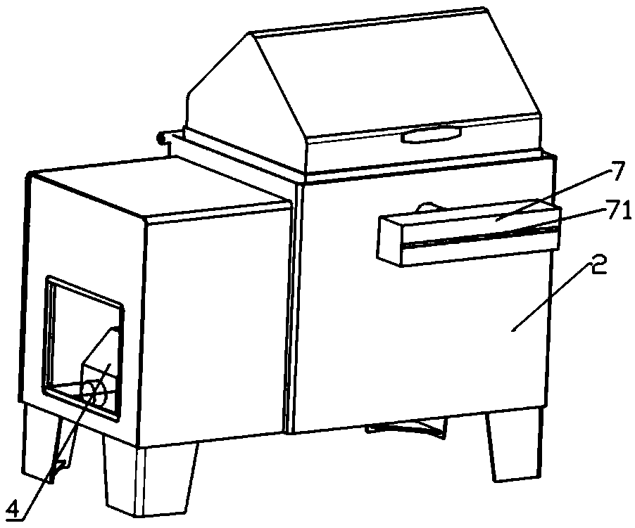
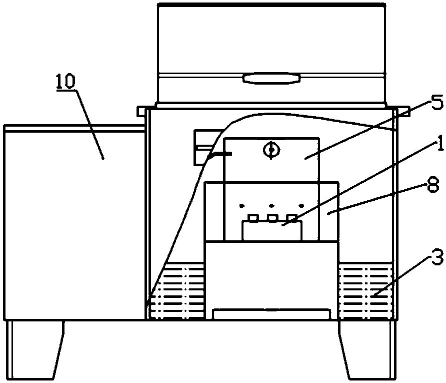
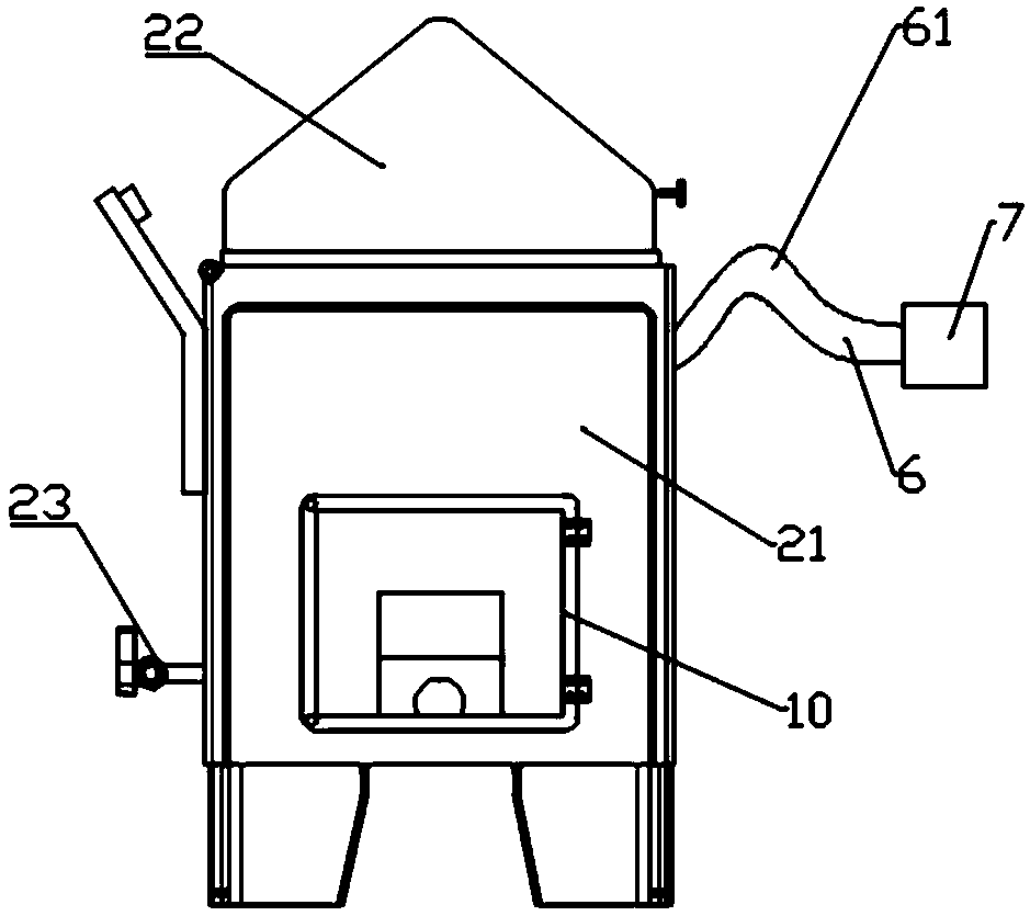
[0037] Embodiment 1: as Figure 1-7 As shown, a thin liquid film generation device on a metal surface includes a thin liquid film generation device, a sample stage, a thin liquid film thickness detection device, and a control computer.
[0038] Wherein, the thin liquid film generating device includes a box body with an atomizer, and a liquid storage tank is arranged in the box body, and the liquid storage tank is connected with the housing of the atomizer through a pump. The shell of the nebulizer is also connected with compressed air, and a mist flow pipe is arranged on the other side of the shell opposite to the compressed air, and the mist flow pipe extends out of the box and is aligned with the sample stage.
[0039] A sample placement area is arranged on the sample platform, and the metal sample is placed on the sample placement area, and the outlet of the mist flow pipe is aligned with the metal sample. Wherein, the outlet of the mist flow pipe can be fixed or adjustabl...
Embodiment 2
[0042] Embodiment 2: as Figure 1-7 As shown in and 13, a thin liquid film generation device on a metal surface includes a thin liquid film generation device, a sample stage, a thin liquid film thickness detection device, and a control computer.
[0043] The thin liquid film generating device includes a box body 2 with an atomizer 1, and a liquid storage tank 3 is arranged in the box body, and the liquid storage tank is connected with the housing 5 of the atomizer through a pump 4, The shell of the nebulizer is also connected with compressed air, and a mist flow pipe 6 is arranged on the other side of the shell opposite to the compressed air, and the mist flow pipe extends out of the box and is aligned with the sample stage.
[0044] Wherein, the outlet of the mist flow pipe is also connected with a mist outlet box 7, and a mist outlet 71 is arranged on the end face of the mist outlet box. And the mist outlet can be seen through the size of the opening of the valve regulator,...
Embodiment 3
[0065] Embodiment 3: as Figure 8-12 This embodiment provides a method for forming a thin liquid film on a metal surface, comprising the following steps:
[0066] The first step: place the metal sample in the sample placement area on the sample stage;
[0067] Step 2: Add electrolyte solution to the calibration position in the liquid storage tank, turn on the heater to heat the electrolyte solution to 25-35°C;
[0068] Step 3: Start the nebulizer, air compressor, circulating peristaltic pump and sample stage in sequence, adjust the atomization volume of the nebulizer to 2.5kg / h~4.5kg / h, and the mist output pressure to 0.1~0.15 Mpa. The platform inclination angle is 0~60°;
[0069] Step 4: Control the displacement of the X-axis guide mechanism, Y-axis guide mechanism and Z guide mechanism through the control computer to adjust the position of the fiber optic probe, run the control software of the fiber optic spectrometer, adjust the position of the fiber optic probe, and opti...
PUM
| Property | Measurement | Unit |
|---|---|---|
| angle | aaaaa | aaaaa |
| thickness | aaaaa | aaaaa |
| angle | aaaaa | aaaaa |
Abstract
Description
Claims
Application Information
 - R&D
- Intellectual Property
- Life Sciences
- Materials
- Tech Scout
- Unparalleled Data Quality
- Higher Quality Content
- 60% Fewer Hallucinations
Browse by: Latest US Patents, China's latest patents, Technical Efficacy Thesaurus, Application Domain, Technology Topic, Popular Technical Reports.
© 2025 PatSnap. All rights reserved.Legal|Privacy policy|Modern Slavery Act Transparency Statement|Sitemap|About US| Contact US: help@patsnap.com


