
Wafer edge reversing device and edge reversing method

A wafer and edge beveling technology, which is applied to machine tools, grinding machines, grinding/polishing equipment, etc., which are suitable for grinding the edge of workpieces, and can solve problems such as the influence of wafer electrical performance, difficulty in edge bevelling, and excessive resistance , to improve product yield, reduce edge chipping, and ensure surface integrity

Pending Publication Date: 2019-01-11
CHENGDU TIMEMAKER CRYSTAL TECH
View PDF6 Cites 3 Cited by
  • Summary
  • Abstract
  • Description
  • Claims
  • Application Information

AI Technical Summary

Problems solved by technology

Specifically: the wafer is fixed on the corresponding jig for high-speed rotation. When the special-shaped grinding wheel is close to the wafer to realize the chamfering process on the edge of the wafer, it is very difficult to fix small-sized wafers, and it is very difficult to process thin slices; in addition, The biggest disadvantage of this method is that the edge of the wafer is ground by grinding wheel grinding. This grinding method is the direct friction between the diamond and the wafer, so it is easy to form new cracks on the edge of the wafer; Rough scratches will also have a corresponding impact on the electrical properties of the wafer, such as excessive resistance
The second method is suitable for the processing of small-sized wafers. The method used is to put the wafers and abrasive sand into the cylinder according to a certain ratio, and then the cylinder is fixed in the centrifuge for rotation; The effect and the grinding sand are attached to the barrel wall of the wafer for grinding to achieve chamfering; when the wafer is deformed by centrifugal force as the size of the wafer decreases, it is difficult to realize the chamfering of the edge; and for large-sized wafers in rolling During the grinding process, it is easy to drop from the upper end of the barrel wall to the lower end to form new cracks on the edge; secondly, it is difficult to ensure that the wafer rolls in the drum to achieve the symmetry of the size of the front and back sides

Method used


Image

  • Wafer edge reversing device and edge reversing method

Examples


Embodiment Construction

[0024] In order to make the objectives, technical solutions, and advantages of the embodiments of the present invention clearer, the technical solutions in the embodiments of the present invention will be described clearly and completely in conjunction with the accompanying drawings in the embodiments of the present invention. Obviously, the described embodiments It is a part of the embodiments of the present invention, but not all the embodiments. Based on the embodiments of the present invention, all other embodiments obtained by those of ordinary skill in the art without creative work shall fall within the protection scope of the present invention.

[0025] In the present invention, unless otherwise clearly defined and defined, the "on" or "under" of the first feature of the second feature may include direct contact between the first and second features, or may include the first and second features Not in direct contact but through other features between them. Moreover, "abov...


PUM

PropertyMeasurementUnit
radiusaaaaaaaaaa

Abstract

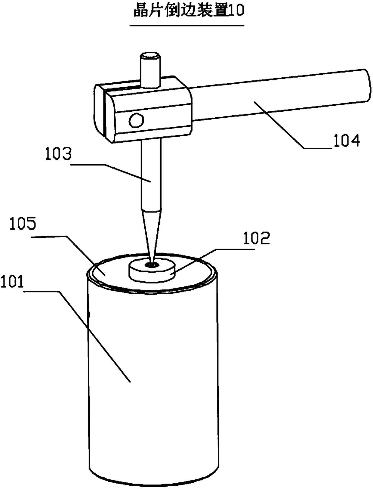
The invention discloses a wafer edge reversing device and an edge reversing method. The device comprises a mold reversing cylinder, a buckling part, a thimble and a bracket; the mold reversing cylinder can be rotated, and the top is of a bowl-shaped mold reversing structure; the buckling part is arranged on the inclined surface of the mold reversing structure; wafers for mold reversing are fixedlyplaced in the buckling part; one end of a point of the thimble is tightly contacted with the surface, far from the mold reversing structure, of the buckling part, and the other end is fixedly connected with the bracket; grinding sand liquid is poured in the mold reversing structure; and the grinding sand liquid can be filled in gaps between the wafers and the mold reversing structure. The devicecan guarantee the surface completeness of reversed edges of the wafers, reduces the edge collapse phenomenon and the surface roughness, and improves the product yield.

Description

Technical field [0001] The invention belongs to the technical field of wafer processing and processing, and particularly relates to a wafer chamfering device and a chamfering method. Background technique [0002] With the rapid development of the electronics industry, the market's demand for crystal materials has increased rapidly, and at the same time higher requirements have been placed on product quality. Due to consideration of the electrical performance requirements of the wafer or the phenomenon of edge collapse due to edge collision during the later processing of the wafer, it is necessary to chamfer the edge of the wafer. Wafer chamfering is to grind the edge of the wafer. [0003] There are two traditional chamfering methods: one is to use a grinding wheel to grind, by processing a corresponding shape of the grinding head jig, and sintering a corresponding number of diamond particles on the jig to form a special-shaped grinding wheel. Specifically: the wafer is fixed on ...

Claims


Application Information

Patent Timeline
Patent Type & Authority Applications(China)
IPC IPC(8): B24B9/06B24B41/06B24B1/00
CPCB24B1/00B24B9/065B24B41/06
Inventor 李辉叶竹之张锐江
Owner CHENGDU TIMEMAKER CRYSTAL TECH
Learn More