
Measurement rotation acceleration sensor and measurement method

A rotational acceleration and sensor technology, applied in the direction of measurement of acceleration, velocity/acceleration/impact measurement, measuring devices, etc., can solve the problems of low precision, difficulty in accurate measurement of physical quantities, measurement of rotational acceleration of the rotating shaft by the sensor, etc., and achieve the goal of simplifying the structure Effect

Active Publication Date: 2015-04-01
HANGZHOU DIANZI UNIV
View PDF4 Cites 7 Cited by
  • Summary
  • Abstract
  • Description
  • Claims
  • Application Information

AI Technical Summary

Problems solved by technology

[0002] Transient rotation speed, that is, rotation acceleration, is one of the most common physical quantities in rotating mechanical systems. It causes torsional vibration of the rotating shaft, which causes vibration and noise in the mechanical system and affects the accuracy of machining. However, it is very difficult to accurately measure this physical quantity. Difficult, the known sensors include circular grating sensors and laser grating sensors. The signals measured by these two sensors are discrete and the accuracy is not high. In addition, there is a permanent magnet rotational acceleration sensor with a cup-shaped rotor structure connected coaxially. , the rotational acceleration signal measured by the sensor is a continuous variation, but because the connection method with the measured shaft must be directly connected coaxially and concentrically, for permanent magnets that have been finalized and are in use and cannot be directly installed coaxially and concentrically In the case of a rotational acceleration sensor, especially when only a part of the middle part of the shaft is exposed without affecting the operation of the original system, the above sensor cannot be used to measure the rotational acceleration of the rotating shaft

Method used


Image

  • Measurement rotation acceleration sensor and measurement method
  • Measurement rotation acceleration sensor and measurement method
  • Measurement rotation acceleration sensor and measurement method

Examples


Embodiment Construction

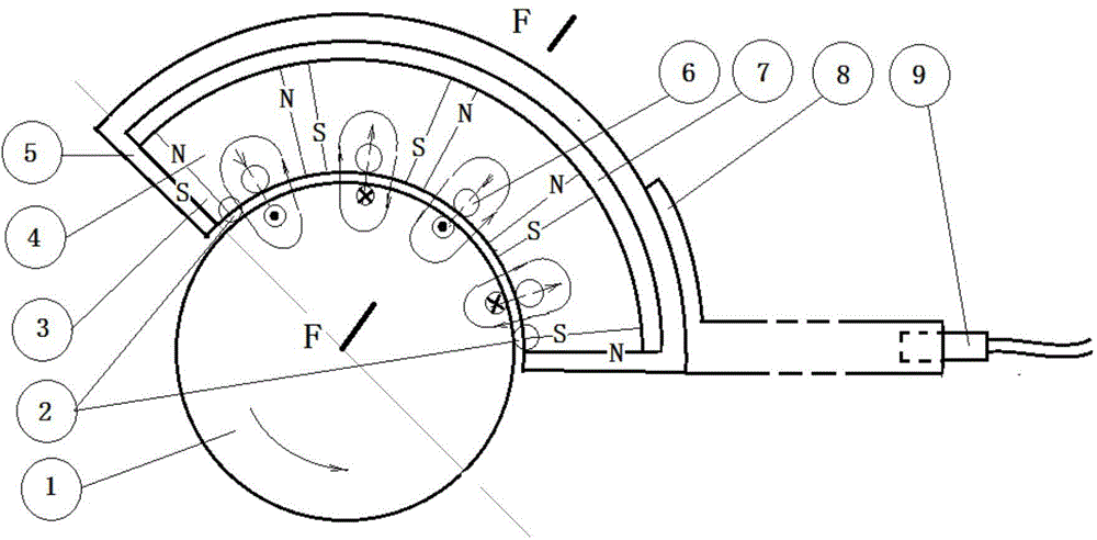
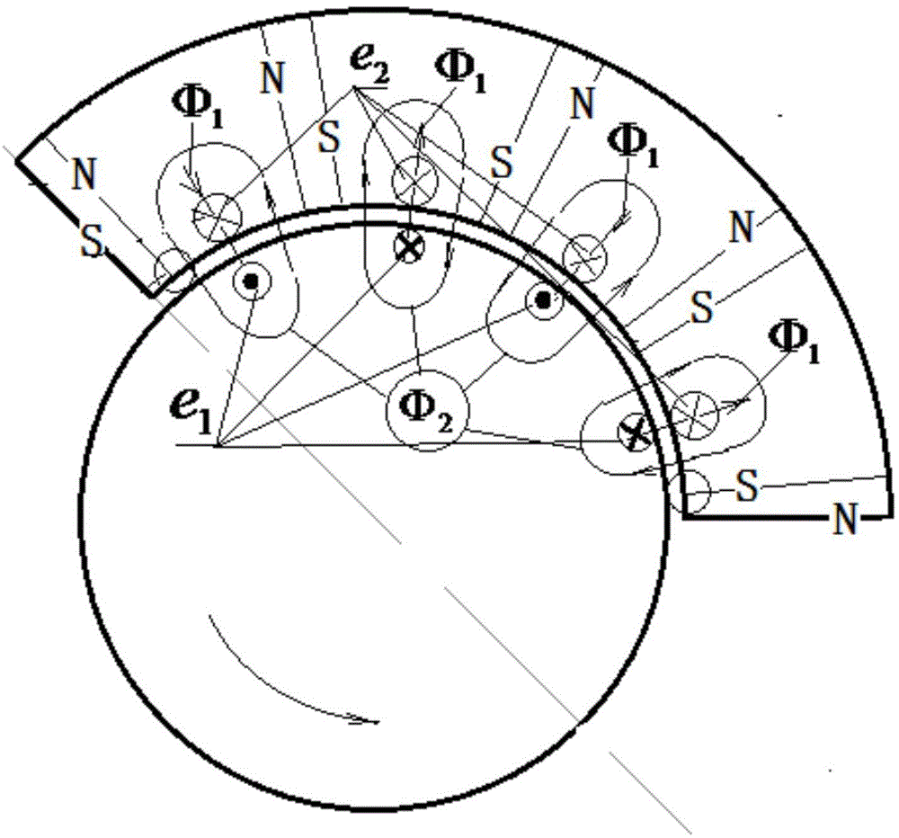
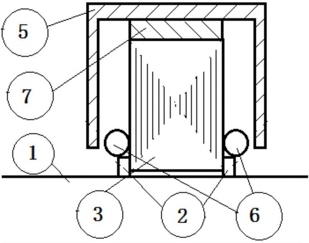
[0022] Such as figure 1 , figure 2 , image 3 As shown, a sensor for measuring rotational acceleration includes a portable part and a rotating part;

[0023] The portable part includes an operating handle 8 , a machine base 5 , an output winding 6 , an elbow gasket 7 , a stator core segment 4 , a permanent magnet 3 , a bearing 2 and an output signal line interface 9 .

[0024] The operating handle 8 is fixedly connected with the machine base 5, and the stator core sections have the same structure, and the stator core sections are spliced ​​to form a fan ring structure, and four bearings 2 are arranged on the inner arc of the fan ring structure. Permanent magnets 3 are arranged between the stator core segments and on the outside of the outermost stator core. The polarities of the adjacent ends of any adjacent permanent magnets are the same. Output windings are arranged in the winding slots of each section of the stator core. The outer arc surface and the outer arc surfa...


PUM


Abstract

The invention relates to a measurement rotation acceleration sensor and a measurement method. The measurement rotation acceleration sensor comprises a portable portion and a rotation portion, wherein the portable portion comprises an operation handle, a support, output windings, elbow sleeve pads, multiple stator core segments, permanent magnetic steels, bearings and an output signal wire interface, the output handle is fixedly connected with the support, the multiple stator core segments are spliced to form a fan-shaped ring structure, an inner arc of the fan-shaped ring structure is provided with four bearings, the permanent magnetic steels are arranged among the adjacent multiple stator core segments and the outer side of the out-most stator core, a winding groove of each stator core segment is internally provided with an output winding, outer arc faces of the stator cores and outer arc faces of the magnetic steels are fixedly connected with the support through the elbow sleeve pads, and the rotation portion is a detected rotation shaft and is taken as one part of an induction winding and a magnetic loop. Compared with a measurement rotation acceleration sensor in the prior art, the measurement rotation acceleration sensor has a simple structure, outputs electromotive force in one-to-one correspondence with the rotation acceleration and further has high precision.

Description

technical field [0001] The invention relates to a rotation acceleration sensor, in particular to a rotation acceleration measurement sensor and a measurement method. Background technique [0002] Transient rotation speed, that is, rotation acceleration, is one of the most common physical quantities in rotating mechanical systems. It causes torsional vibration of the rotating shaft, which causes vibration and noise in the mechanical system and affects the accuracy of machining. However, it is very difficult to accurately measure this physical quantity. Difficult, the known sensors include circular grating sensors and laser grating sensors. The signals measured by these two sensors are discrete and the accuracy is not high. In addition, there is a permanent magnet rotational acceleration sensor with a cup-shaped rotor structure connected coaxially. , the rotational acceleration signal measured by the sensor is a continuous variation, but because the connection method with the ...

Claims


Application Information

Patent Timeline
Patent Type & Authority Applications(China)
IPC IPC(8): G01P15/105
Inventor 冯浩赵浩丁立军张娟娟
Owner HANGZHOU DIANZI UNIV
Learn More