
Compact and vertical adjusting unit for headlight mounted in vehicle

A technology for adjusting units, headlights, applied in the direction of headlights, components of lighting devices, lighting and heating equipment, etc.

Inactive Publication Date: 2012-10-31
AUTOMOTIVE LIGHTING REUTLINGEN GMBH
View PDF0 Cites 8 Cited by
  • Summary
  • Abstract
  • Description
  • Claims
  • Application Information

AI Technical Summary

Problems solved by technology

As a result, the axis of rotation of the vertical adjuster for the dipped beam unit can only be arranged perpendicular to the direction of travel in very large headlight housings

Method used


Image

  • Compact and vertical adjusting unit for headlight mounted in vehicle
  • Compact and vertical adjusting unit for headlight mounted in vehicle
  • Compact and vertical adjusting unit for headlight mounted in vehicle

Examples


Embodiment Construction

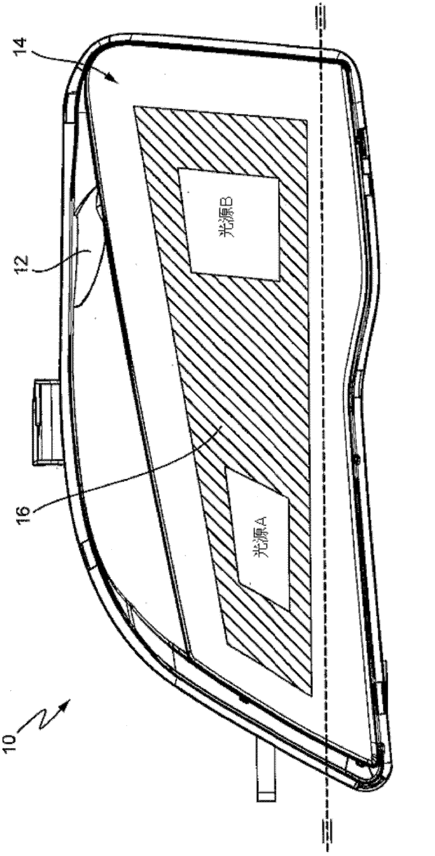
[0026] exist figure 1 A headlight 10 is shown in , which contains two light sources A and B, a headlight housing 12 and a control unit 14 . The two light sources A and B are arranged here on the carrier element 16 . Light source A refers to basic light. The light source B is designed as a so-called point light. Light source A thus provides widely dispersed elementary light below the horizontal light / dark boundary, while light source B provides the light path (spot functionality) of the light. The two light sources A and B, from which the light distribution of the headlight 10 is formed, can be positioned relative to each other by means of an adjustment unit 14 here.

[0027] exist figure 2 The adjusting unit 14 can clearly be seen in FIG. 2 , which has a carrier element 16 carrying the two light sources A and B. In FIG. In this case, the adjustment unit 14 is arranged behind the carrier element 16 in the headlight and thus in the figure 1cannot be seen in . The carrier...


PUM


Abstract

The invention relates to an adjusting unit applicable to a headlight, particularly to a headlight having two light sources (A and B). The adjusting unit comprises a basal body member and a sliding block relative to the basal body member and capable of being adjusted along the adjusting direction, with the sliding block being used for adjusting the bearing element loaded with two light sources around the horizontal axis. The adjusting unit further comprises a first adjusting device for adjusting the sliding block and a second adjusting device, wherein the second adjusting device is used for adjusting the partition bearing the second light source B of the bearing element around the axis extending vertically to the horizontal axis; the second adjusting device comprises a rotary section of the basic component side, the sliding block section of the sliding block side, and a rotary coupler. Therefore, although the rotary section and the sliding block section are connected in a rotary manner, they can be arranged in a mutually and relatively moving manner thanks to the rotary coupler. In addition, the invention discloses a headlight applicable to vehicles. The headlight comprises a light source A arranged upon the bearing element and a light source B arranged upon the partition of the bearing element. The headlight is characterized in that: the headlight comprises an adjusting unit; the bearing element having light source A and light source B can be adjusted around the horizontal axis via the first adjusting device; and only the partition bearing the light source B of the bearing element can be adjusted around the axis extending vertically to the horizontal axis via the second adjusting device.

Description

technical field [0001] The invention relates to an adjustment unit for a headlight, in particular for a motor vehicle headlight with two light sources, and also to a headlight with two light sources, the front headlight comprising such an adjustment unit. Background technique [0002] Modern headlights have an ever-increasing "sweep angle". The rear sweep angle refers to the oblique position of the headlight relative to the direction of travel, ie the reflector of the light source is arranged offset in the direction of travel, but also points in the direction of travel. The reason for such a large sweep angle lies primarily in the car design, where the dynamism of the car is emphasized by the design of the headlights, which becomes increasingly important here. On the other hand, this trend leads to ever larger components in LED headlights. As a result, the dipped beam function of the headlights is more and more often produced by a separate light source. Thus, for example,...

Claims


Application Information

Patent Timeline
Patent Type & Authority Applications(China)
IPC IPC(8): F21V14/02B60Q1/068F21W101/10
CPCF21V14/02B60Q2200/36B60Q1/0683
Inventor 迈克尔・迪尔尼古拉・弗拉多夫里德里克・绍韦克尔
Owner AUTOMOTIVE LIGHTING REUTLINGEN GMBH
Learn More