
Light beam transmission stabilizing device

A technology for stabilizing devices and beams, which is applied in the field of beam transmission, and can solve the problem that the control algorithm of the beam transmission device is complicated, the adjustment of position deviation and pointing deviation cannot be satisfied at the same time, and the adjustment frequency and large adjustment range of a single two-dimensional controllable mirror are not high. and other problems to achieve the effect of simplifying the control algorithm and improving the control efficiency

Inactive Publication Date: 2012-07-11
INST OF OPTICS & ELECTRONICS - CHINESE ACAD OF SCI
View PDF5 Cites 6 Cited by
  • Summary
  • Abstract
  • Description
  • Claims
  • Application Information

AI Technical Summary

Problems solved by technology

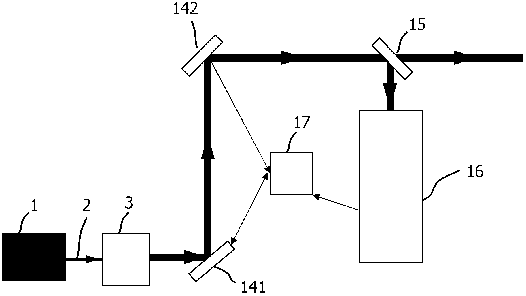
Therefore, a single two-dimensional controllable mirror cannot meet the performance requirements of high adjustment frequency and large adjustment range required by the beam control unit at the same time, that is, it cannot meet the adjustment of position deviation and pointing deviation at the same time; and the patent structure adopted by the first A beam control unit 141 and a second beam control unit 142 form a beam control module, and the adjustment of the beam position deviation and pointing deviation affects each other, that is, the first beam control unit 141 will adjust the beam pointing deviation while adjusting the beam position deviation The second beam control unit 142 will affect the position deviation of the beam while adjusting the pointing deviation of the beam, which makes the control algorithm of the beam transmission device more complicated

Method used


Image

  • Light beam transmission stabilizing device
  • Light beam transmission stabilizing device
  • Light beam transmission stabilizing device

Examples


Embodiment Construction

[0049] The implementation of the present invention will be further described in detail below in conjunction with the accompanying drawings and specific examples.

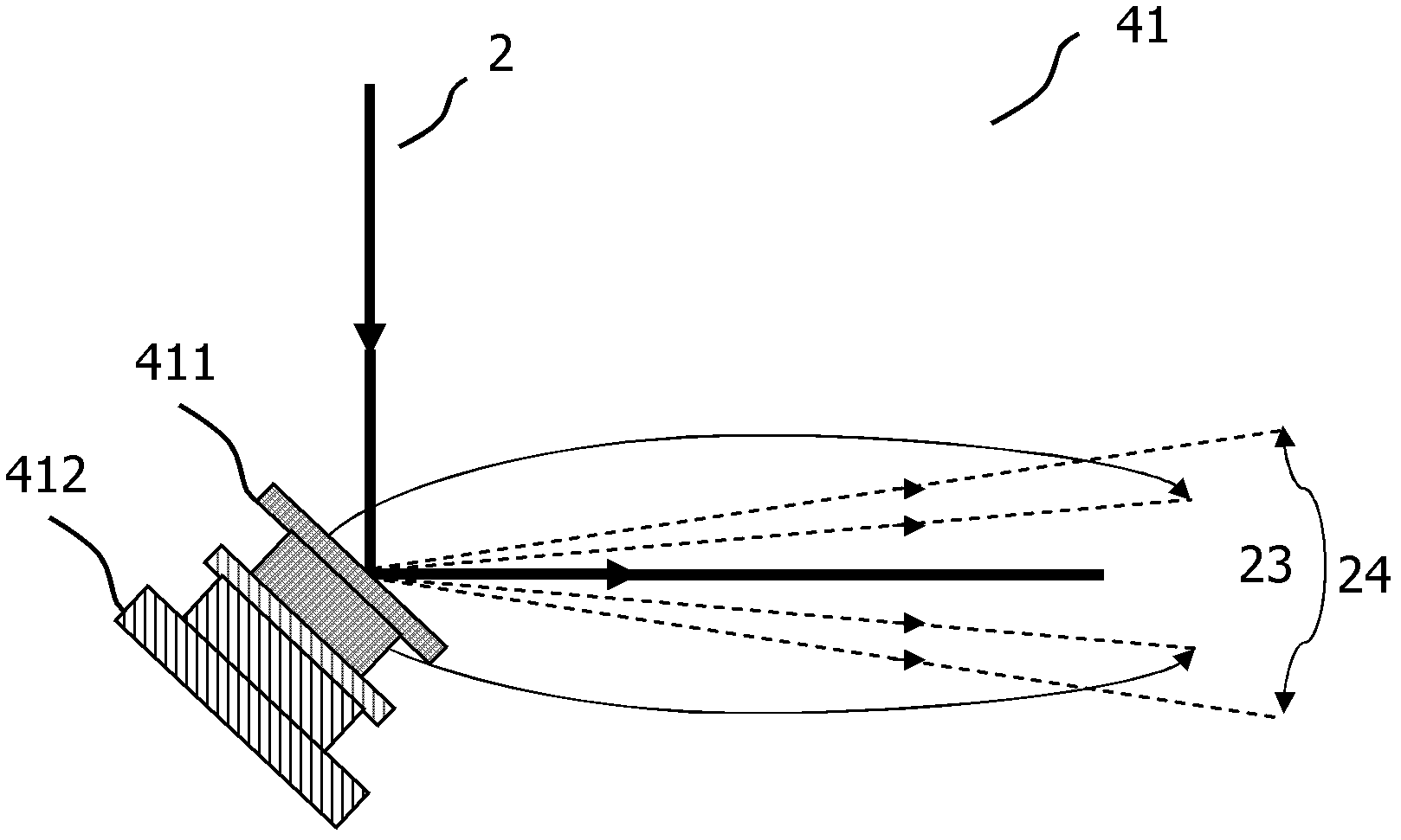
[0050] image 3 It is a schematic structural diagram of the first light beam control unit 41 described in the present invention. The first light beam control unit 41 used in the present invention is composed of a high-frequency two-dimensional steerable mirror 411 with a fast response frequency and a small adjustment range and a low-frequency two-dimensional steerable mirror 412 with a slow response frequency and a large adjustment range. The high-frequency two-dimensional steerable mirror 411 is fixed on the low-frequency two-dimensional steerable mirror 412 . By controlling the rotation angles of the high-frequency two-dimensional steerable mirror 411 and the low-frequency two-dimensional steerable mirror 412 , the direction of the incident beam 2 after being reflected by the first beam control unit 41 can be cha...


PUM


Abstract

The invention provides a light beam transmission stabilizing device for transmitting an emitted light beam from a laser to an illumination system, and a light beam control module is arranged on the transmission optical path, wherein the light beam control module comprises a first light beam control unit (41), a second light beam control unit (42), and a third light beam control unit (43). A spectroscope (44) is arranged on an emergent light path of the light beam control module, the spectroscope (44) divides the light beam into two beams, wherein one light beam enters an illumination system (5), and the other beam enters a light beam measuring module (45). The light beam measuring module (45) is connected with a controller (46) for supplying measured data to the controller (46). The controller (46) are connected with the first light beam control unit (41), the second light beam control unit (42) and the third light beam control unit (43) of the light beam control module for supplying control signal to the light beam control module to regulate the light beam position deviation and directional deviation.

Description

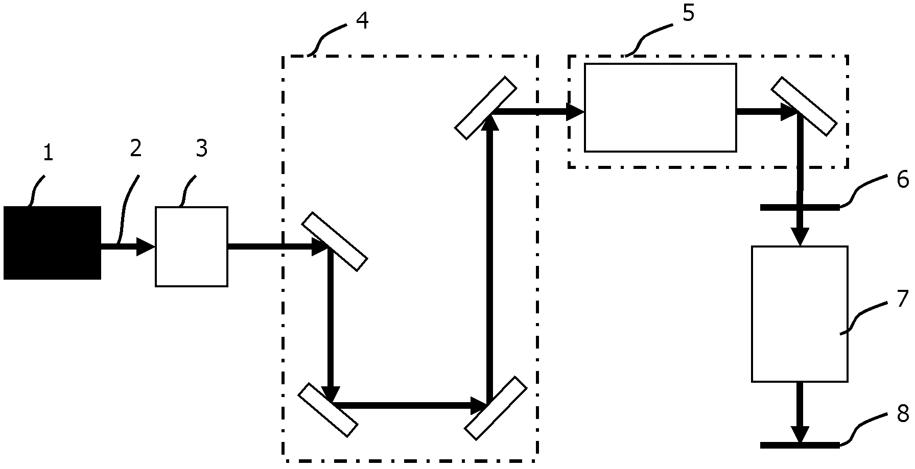
technical field [0001] The invention relates to the field of beam transmission, in particular to a beam transmission stabilizing device. Background technique [0002] Optical projection lithography uses the principle of optical projection imaging to transfer the integrated circuit (IC) pattern on the mask to the rubber-coated silicon wafer by step-and-repeat or step-and-scan exposure. [0003] figure 1 Shown is an optical projection lithography system, which mainly includes a beam expansion and shaping system 3 , a beam transmission system 4 , a lithography illumination system 5 , a mask 6 , a lithography objective lens 7 , and a silicon wafer 8 . The light beam 2 is emitted by the light source 1 that provides radiant light energy, and then passes through the beam expansion and shaping system 3 in turn, the beam 2 that is expanded and shaped, and the beam transmission system 4 enters the lithography lighting system 5, and the lithography lighting system 5 provides the mask ...

Claims


Application Information

Patent Timeline
IPC IPC(8): G03F7/20G02B26/08
Inventor 甘大春王建林妩媚张海波廖志杰
Owner INST OF OPTICS & ELECTRONICS - CHINESE ACAD OF SCI
Learn More