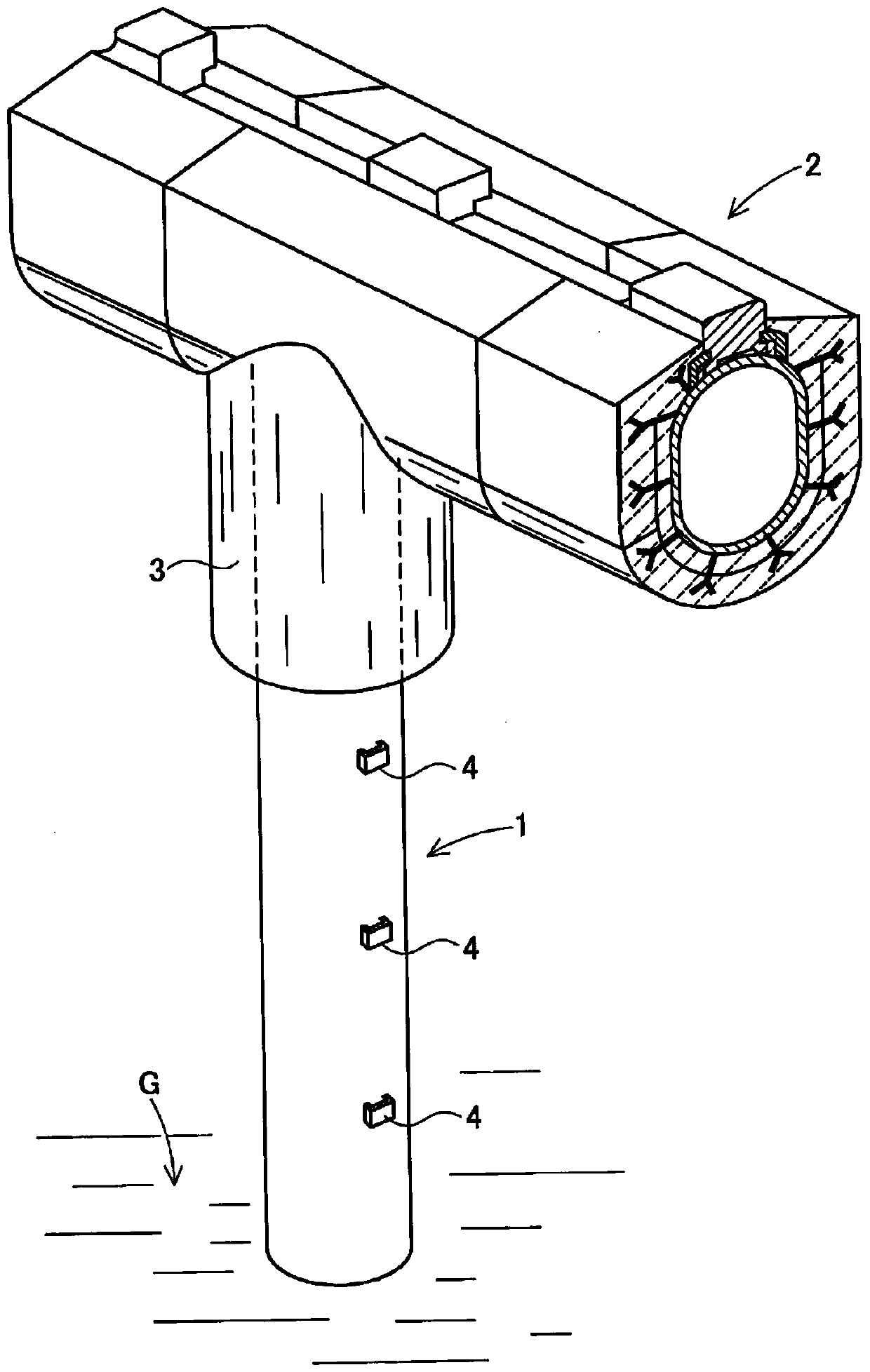
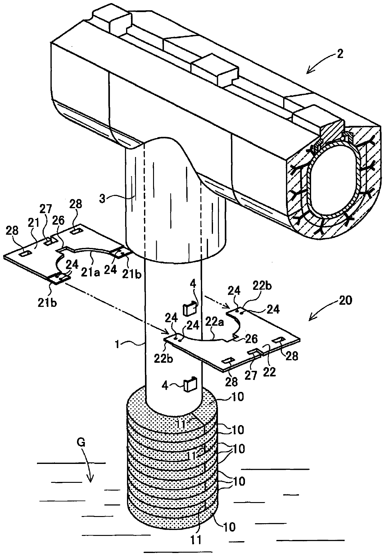
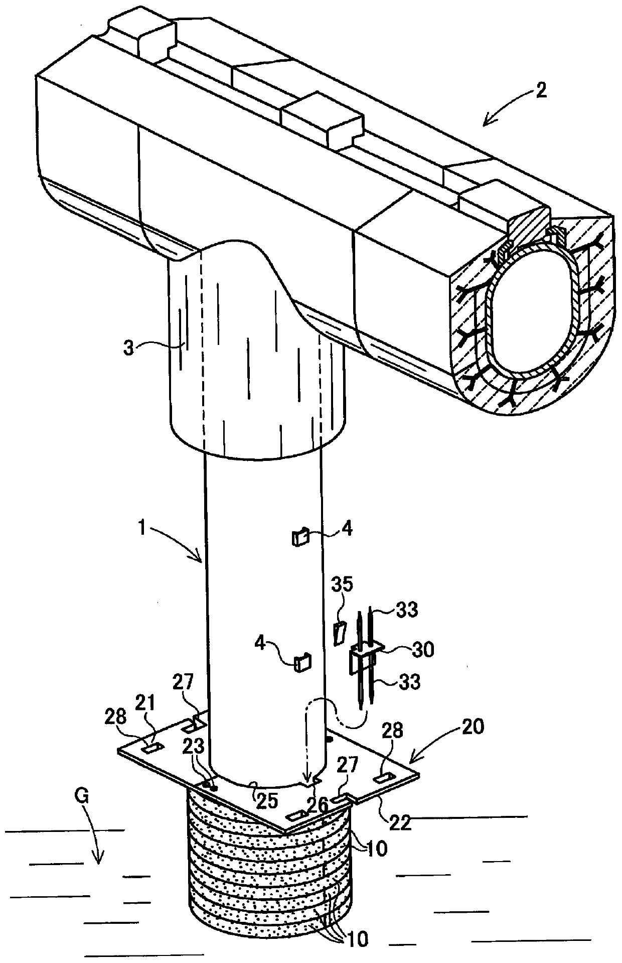
Construction method of slideway pipe and its thermal insulation protection component
A technology for protecting components and construction methods, which is applied in the direction of pipeline protection, pipeline protection through heat insulation, pipes/pipe joints/fittings, etc., and can solve problems such as construction of unrecorded heat insulation materials
- Summary
- Abstract
- Description
- Claims
- Application Information
AI Technical Summary
Problems solved by technology
Method used
Image
Examples
Embodiment 1
[0163]Polycrystalline alumina / silica fibers containing 72% by mass of alumina and 28% by mass of silica, which have an average fiber diameter of 5.5 μm and do not substantially contain fibers with a fiber diameter of 3 μm or less, are aggregated and needle punched. The resulting needle-punched blanket (trade name MAFTEC manufactured by Mitsubishi Chemical Corporation) TM MLS, thickness 25mm, needle punch density 5 dozen / cm 2 , Bulk density 128kg / m 3 (0.128g / cm 3 ), surface density 3200g / m 2 ) punching process into a ring shape with an outer diameter (diameter) of 390 mm and an inner diameter (diameter) of 270 mm to manufacture an annular needle-punched blanket 10 .
[0164] The residual surface pressure ratio after the cycle test was measured for the ring-shaped needle-punched carpet 10 under the conditions described below, and the residual surface pressure ratio was 33%.
[0165] Conditions: The ring-shaped needle-punched blanket 10 calcined at 1400° C. for 12 hours was ...
Embodiment 2
[0178] [Example 2 (compressing the third compression layer to a stronger degree)]
[0179] The same construction as in Example 1 was performed except that the number of annular needle-punched carpet sheets in the third compression layer L-3 was 28, the compression height was 560 mm, and the compression rate was 20%. The average bulk density and interplane pressure of L-1, L-2, and L-3 (including the uppermost ring-shaped needle-punched carpet 10 ) were measured. The results are shown in Table 1.
Embodiment 3
[0185] Make the ring-shaped needle-punched blanket 10 laminated compacts with the same compression rate as in Example 1, coat the surface with mortar with a thickness of about 3mm, and wind the blanket impregnated with the liquid containing the oxide-containing precursor in the entire thickness direction (relative to The amount of moisture in 100 parts by mass of inorganic fibers is 200 parts by mass, the amount of oxide precursor attached to 100 parts by mass of inorganic fibers is 18 parts by mass (in terms of oxides), and the molar ratio of Al and Ca in the impregnated part (Al / Ca) is 64 and bulk density is 0.41g / cm 3 ), the oxide-containing precursor liquid is to add calcium acetate monohydrate to the alumina sol solution using acetic acid as a dispersant in such a way that the molar ratio of Al to Ca (Al / Ca) becomes 12, and the oxide The converted solid content concentration was adjusted to 7.0% by mass. Calcination was carried out under the conditions of a heating rate...
PUM
| Property | Measurement | Unit |
|---|---|---|
| density | aaaaa | aaaaa |
| density | aaaaa | aaaaa |
| diameter | aaaaa | aaaaa |
Abstract
Description
Claims
Application Information
 - R&D
- Intellectual Property
- Life Sciences
- Materials
- Tech Scout
- Unparalleled Data Quality
- Higher Quality Content
- 60% Fewer Hallucinations
Browse by: Latest US Patents, China's latest patents, Technical Efficacy Thesaurus, Application Domain, Technology Topic, Popular Technical Reports.
© 2025 PatSnap. All rights reserved.Legal|Privacy policy|Modern Slavery Act Transparency Statement|Sitemap|About US| Contact US: help@patsnap.com


