
Gradient coating cutter and preparation method thereof

A gradient coating and cutting tool technology, applied in the direction of coating, metal material coating process, etc., can solve the problems such as the toughness of the cutting tool coating needs to be further improved, the bonding strength between the coatings is low, and the brittleness of the ceramic cutting tool is high. Effects of thermal stability and wear resistance, high hardness, good toughness

Active Publication Date: 2018-06-15
SOUTHEAST UNIV
View PDF9 Cites 19 Cited by
  • Summary
  • Abstract
  • Description
  • Claims
  • Application Information

AI Technical Summary

Problems solved by technology

However, the thickness of the coating prepared by the above method is limited, and the bonding strength between the coatings is low
The Chinese invention patent with the application number 03112232.9 discloses a gradient functional ceramic cutting tool material and its preparation method. The gradient functional ceramic cutting tool material has a symmetrical bidirectional composition distribution structure, but the ceramic cutting tool itself has the disadvantage of high brittleness.
The Chinese invention patent with the application number 201710541381.8 discloses a laser cladding graphene-ceramic self-lubricating coating tool and its preparation method. The rake face of the tool is a graphene-ceramic self-lubricating coating, which can realize the self-lubricating function, but the tool coating toughness needs to be further improved

Method used


Image

  • Gradient coating cutter and preparation method thereof

Examples


Embodiment 1

[0022] Example 1: The gradient coating tool is prepared on the rake face of the tool by laser cladding, and the specific preparation steps are:

[0023] (1) Pre-treatment: place the tool in alcohol and acetone solutions for 30 minutes and ultrasonically clean it for degreasing treatment;

[0024] (2) Cladding cemented carbide layer: MoS 2 , BN and LaF 3 The powder is added to the cemented carbide mixed powder to configure the mixed powder, and the weight percentage of its main components is: 80% WC, 8% TiC, 6% Co, 1% TaC, 2% MoS 2 , 1% BN, 2% LaF 3 , the sum of the weight percentages of each material is 100%; put the prepared cemented carbide mixed powder into the powder feeder, and adjust the powder feeding rate of the powder feeder to 20g / cm 3 ; Using CO with a wavelength of 10.6 μm 2 Laser cladding cemented carbide mixed powder on the rake face of the tool, laser cladding is carried out by synchronous powder feeding, powder feeding gas and shielding gas are both argon; ...

Embodiment 2

[0028] Example 2: The preparation method of the gradient coating tool in this example is prepared on the rake face of the tool by laser cladding. The difference from Example 1 is that the weight percentage of the material components in steps (2) and (3) , coating thickness and laser processing parameters are different from Example 1, and the gradient coating thickness in step (4) is different from Example 1. The specific preparation steps of the tool are as follows:

[0029] (1) Pre-treatment: place the tool in alcohol and acetone solutions for 30 minutes and ultrasonically clean it for degreasing treatment;

[0030] (2) Cladding cemented carbide layer: MoS 2 , BN and LaF 3 The powder is added to the cemented carbide mixed powder to configure the mixed powder, and the weight percentage of its main components is: 65% WC, 15% TiC, 10% Co, 2% TaC, 3% MoS 2 , 2% BN, 3% LaF 3 , the sum of the weight percentages of each material is 100%; put the prepared cemented carbide mixed p...


PUM


Abstract

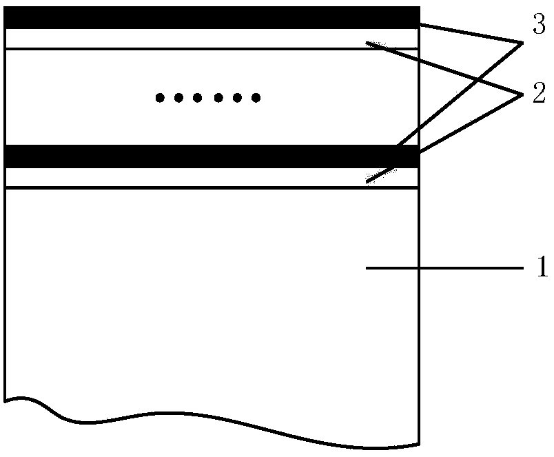
The invention discloses a gradient coating cutter and a preparation method thereof. A basal body material of the gradient coating cutter is high-speed steel; a multilayer coating layer is arranged onthe surface of a basal body; and the coating layer is a gradient laminated coating layer of alternating hard alloy layers, added with MoS2, BN and LaF3, and Al2O3 base ceramic layers. The cutter coating layer is prepared by adopting a laser cladding method; and the preparation steps are (1) pretreatment, (2) cladding of the hard alloy layers, (3) cladding of the Al2O3 base ceramic layers, (4) alternate cladding of the hard alloy layers and the Al2O3 base ceramic layers, and (5) aftertreatment. Compared with the prior art, the gradient coating layer on the surface of a cutter has the characteristics of Al2O3 base ceramic and hard alloys, and achieves higher hardness and excellent toughness; and through adding of MoS2, BN and LaF3, the cutter achieves excellent self-lubrication effect in wider cutting temperature range. The coating cutter can be applied to dry cutting and cutting of difficultly machined materials.

Description

technical field [0001] The invention relates to the field of mechanical cutting tool manufacturing, in particular to a gradient coating tool and a preparation method thereof. Background technique [0002] Due to the high cost of cutting fluid and environmental pollution, dry cutting has become a research hotspot in green processing. However, during high-speed dry cutting, the friction between the tool and chips on the rake face is extremely severe, which generates a lot of heat, resulting in rapid wear of the tool. Therefore, there is an urgent need to research and develop new tools with no pollution, high efficiency, high hardness and high wear resistance, so as to reduce friction and improve tool life. [0003] At present, the cutting tool materials widely used at home and abroad mainly include high-speed steel, cemented carbide, ceramics and diamond tools. Among them, high-speed steel has poor thermal conductivity, low hardness, and poor wear resistance, so it is not su...

Claims


Application Information

Patent Timeline
IPC IPC(8): C23C24/10
Inventor 邢佑强王孟雅李想胡若愚黄开靓
Owner SOUTHEAST UNIV
Learn More