
Nuclear test specimen automatic separation device

An automatic separation and separation column technology, applied in separation methods, preparation of samples for testing, liquid separation of solid adsorbents, etc., can solve the problems of long sample separation time, short instrument life, long reagent flow time, etc., to avoid crossover. Risk of contamination, improving the accuracy of liquid extraction, and reducing the effect of separation time

Pending Publication Date: 2018-06-01
CHINA INSTITUTE OF ATOMIC ENERGY
View PDF8 Cites 0 Cited by
  • Summary
  • Abstract
  • Description
  • Claims
  • Application Information

AI Technical Summary

Problems solved by technology

For example, during the process operation of the post-processing pilot plant, the separation task of the neptunium post in the analysis laboratory is heavy, and the separation time of each sample is long, and the speed of separation and pretreatment cannot keep up with the speed of sample collection, resulting in the accumulation of samples at the post. Seriously, the current manual separation operation mode can no longer meet the existing requirements
For future 200-ton or even larger post-processing plants, the analysis tasks will be more arduous. If the analysis tasks are to be completed, a large number of analysis staff and analysis positions will inevitably be added. This is undoubtedly the development of future analysis laboratories. is unfavorable
[0003] With the development of science and technology, automated sample pretreatment equipment has entered more and more fields. The automated sample pretreatment equipment currently on the market is mostly applicable to samples from industries such as the environment, agricultural products, and biomedicine. Compared with the samples of the industrial spent fuel reprocessing process, the reprocessing process samples have their particularity: (1) The sample matrix is ​​nitric acid, which is volatile and highly corrosive, and the instruments and equipment on the market basically do not have corrosion resistance. It will be corroded and damaged in a short period of time, resulting in a short life of the instrument;
[0004] (2) The sample is radioactive, and the separation operation needs to be carried out in a closed glove box
The space inside the glove is limited, which not only makes it inconvenient to arrange the equipment, but also makes it difficult to maintain the equipment in the later stage;
[0005] (3) The sample separation process is unique. Since the separation methods for separating neptunium and plutonium in the post-processing process are all specially developed, the separation process requires equipment with the function of diluting the primary eluent and then carrying the second sample for separation. There is no separate device that fully supports this feature
[0006] (4) Equipment using XYZ robotic arm mode does not have the separation function of extraction chromatography column
[0007] (5) The equipment adopts an integrated design, the reagent bottles are far away, the reagents flow in the transmission pipeline for a long time, the separation efficiency and the accuracy of liquid extraction are poor

Method used


Image

  • Nuclear test specimen automatic separation device
  • Nuclear test specimen automatic separation device
  • Nuclear test specimen automatic separation device

Examples


Embodiment 1

[0080] In this example, the above-mentioned experimental equipment and collection mode 1 were used for experimental operation, and the specific parameters were: the sample contained 61g / L U, 1.0×10 -4 g / L Np, 4×10 -7 g / L Pu and 3mol / LHNO 3 , the reagent is HNO 3 、HON 3 -HF and H 2 C 2 o 4 、H 2 O. The specific steps are as follows:

[0081] (1) Take 1ml of sample, add 0.2ml ferrous sulfamate reducing agent and put it into the sample bottle, place the sample bottle on the sample bottle holder;

[0082] (2) Turn on the device, start the separation software, and the software running program is:

[0083] aPretreatment with 5ml HNO 3 Add to the extraction column 1 at a flow rate of 1mi / min, and wait for 4 seconds;

[0084] b. Loading Add 2ml of sample into the extraction column 1 at a flow rate of 1ml / min, and wait for 4 seconds;

[0085] c rinse with 10ml HNO 3 Add to the extraction column 1 at a flow rate of 1ml / min, and wait for 4 seconds;

[0086] dElute with 10ml H...

Embodiment 2

[0099] In this embodiment, the above-mentioned experimental equipment and collection mode 3 are used for experimental operation. The specific parameters are: the sample is 16.2ng / ml plutonium solution (3M nitric acid system), and the reagent is HNO 3 、HON 3 -HF and H 2 O. Specific steps are as follows:

[0100] (1) Take 0.3ml of sample in a 5ml sample bottle, add 0.1ml of 0.5M ferrous sulfamate, shake slightly evenly, and place it in the sample position of the sample bottle holder;

[0101] (2) Turn on the device, start the separation software, and the software running program is:

[0102] aPretreatment with 5ml HNO 3 Add to the extraction column 1 at a flow rate of 1mi / min, and wait for 4 seconds;

[0103] b. Loading Add 2ml of sample into the extraction column 1 at a flow rate of 1ml / min, and wait for 4 seconds;

[0104] c Elution with 1ml HNO 3 - HF is added to the extraction column 1 at a flow rate of 1ml / min, the collection tube is at position 1, and wait for 4 sec...


PUM


Abstract

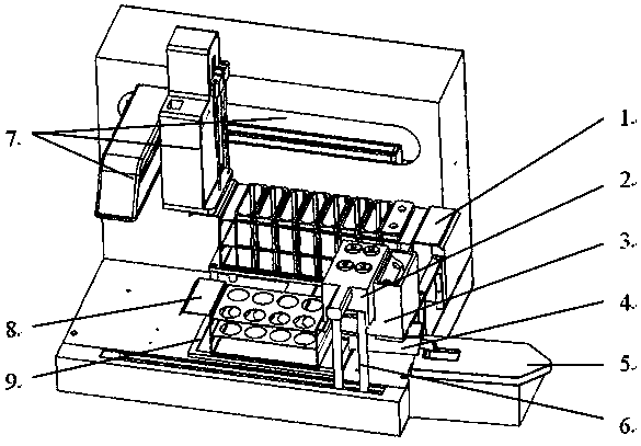
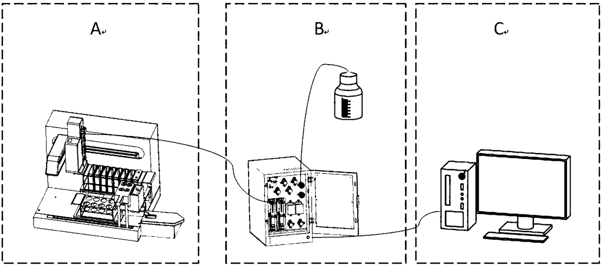
The invention belongs to the field of nuclear fuel post treatment, and particularly relates to a nuclear test specimen automatic separation device. The device comprises a mechanical arm separation module, a pump module and a control system module, wherein the pump module is connected to the mechanical arm separation module and is used for reagent addition by the mechanical arm separation module and the sampling by a sampling pin; the control system module is connected to the mechanical arm separation module and the pump module, and is used for controlling the automatic operation of the pump module and a mechanical arm platform, so that the space used in a glove box is reduced; the repair and the maintenance are convenient; the flowing time of reagents and test specimens is reduced; the liquid taking precision is improved; the separation time is shortened; the efficiency is improved; the secondary sample carrying separation function after the primary eluant dilution is realized.

Description

technical field [0001] The application belongs to the field of nuclear fuel reprocessing technology, and in particular relates to an automatic separation device for nuclear samples in a glove box. Background technique [0002] At present, a large part of the analysis methods for neptunium, uranium, and plutonium in my country's post-processing analysis laboratories require pre-sample pretreatment, that is, to separate and extract the analysis objects to reduce the interference of other elements in the sample before the sample can be processed. Enter the instrument measurement and then get the analysis data. For example, during the process operation of the post-processing pilot plant, the separation task of the neptunium post in the analytical laboratory is heavy, and the separation time of each sample is long, and the speed of separation pretreatment cannot keep up with the speed of sample collection, resulting in very heavy accumulation of samples in the post. Seriously, th...

Claims


Application Information

Patent Timeline
IPC IPC(8): G01N1/38G21F9/12B01D15/10
CPCB01D15/10G21F9/125G01N1/38
Inventor 应浙聪赵胜洋苏玉兰金花
Owner CHINA INSTITUTE OF ATOMIC ENERGY
Learn More