
Self-locking surge protection device

A technology of surge protection and surge protector, which is applied in the direction of emergency protection circuit devices, circuit devices, emergency protection circuit devices for limiting overcurrent/overvoltage, etc. And problems such as cumbersome disassembly process and damage to outdoor electronic products, to achieve good protection, improve use safety, and improve operational performance

Pending Publication Date: 2018-03-06
东莞市领亚电线电缆有限公司
View PDF0 Cites 0 Cited by
  • Summary
  • Abstract
  • Description
  • Claims
  • Application Information

AI Technical Summary

Problems solved by technology

[0003] In the installation process of the lightning protection device in the prior art, it is necessary to use external screws and other fasteners to install the lightning protection device on the open-air electronic product. The installation and disassembly process is extremely cumbersome, time-consuming and laborious, and extremely inconvenient to use.
In addition, due to the unreasonable structural design of the existing lightning protector, when the existing lightning protector is damaged, the operator often cannot know that the lightning protector has been damaged, that is, the user cannot monitor whether the lightning protector is damaged, so it will Due to the damage of the lightning protector, the open-air electronic products are damaged by lightning strikes. If the operators are arranged to inspect the lightning protector regularly, the labor cost will also increase greatly.

Method used


Image

  • Self-locking surge protection device
  • Self-locking surge protection device
  • Self-locking surge protection device

Examples


Embodiment 1

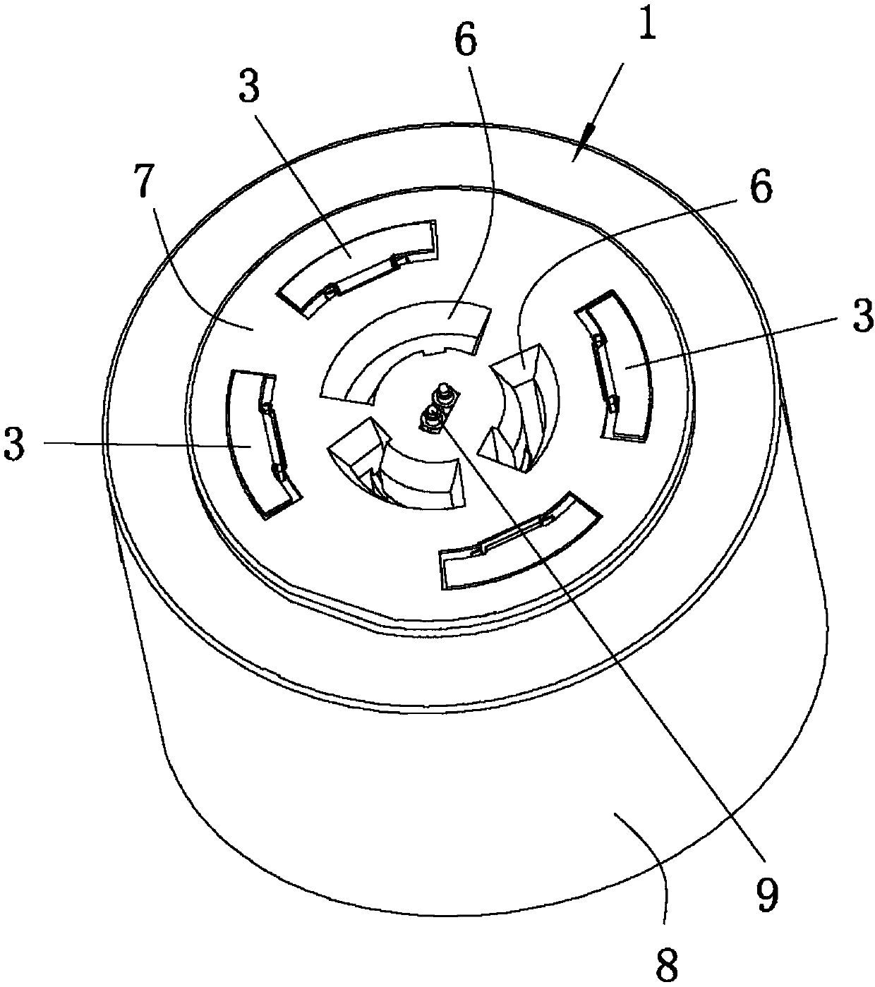
[0035] see Figure 1 to Figure 4 As shown, a self-locking surge protection device of the present invention includes a first insulator 1, a surge protector (not shown in the figure) and a sensor (shown in the figure) installed on the first insulator 1, The sensor is used to detect the on-off of the surge protector; the first insulator 1 is also equipped with a plurality of first power terminals 2 and a plurality of first signal terminals 3, and each first power terminal 2 is provided with a first The contact part 4, each first signal terminal 3 is provided with a second contact part 5, all the first contact parts 4 and all the second contact parts 5 reveal the same side of the first insulator 1, and the first insulator 1 is provided with A plurality of concave holes 6 and a plurality of slots (not shown in the figure), the first insulator 1 is provided with a reference outer surface 7, and all the first contact portions 4 and all second contact portions 5 expose the reference o...

Embodiment 2

[0052] In this embodiment, the casing 8 includes the following components by weight: 30 parts of low-density polyethylene, 10 parts of bisphenol A epoxy resin, 12 parts of phenolic resin, 3 parts of silicone resin, magnesium sulfate whiskers 2 parts, 2 parts of nano antimony trioxide, 1 part of silicon carbide, 5 parts of superfine alumina powder, 4 parts of white carbon black, 3 parts of epoxy fatty acid butyl ester, 4 parts of phthalate, diphenyl peroxide 0.2 parts of formyl, 5 parts of polysiloxane, 2 parts of calcium lignosulfonate to obtain a mixture.

[0053] Preferably, the preparation method of the casing 8 includes the following steps:

[0054] (1) Add each component in proportion to the reaction vessel and mix evenly, heat to 90°C for 120 minutes to obtain the mixture;

[0055] (2) The mixture is extruded into a molten state, then extruded into an injection molding machine, and injection molded to obtain the casing 8 .

[0056] The rest of the content of this embod...

Embodiment 3

[0058] In the present embodiment, the casing 8 includes the following components by weight: 35 parts of low-density polyethylene, 15 parts of bisphenol A epoxy resin, 18 parts of phenolic resin, 6 parts of silicone resin, magnesium sulfate whiskers 3 parts, 3 parts of nano antimony trioxide, 2 parts of silicon carbide, 8 parts of superfine alumina powder, 8 parts of white carbon black, 6 parts of epoxy fatty acid butyl ester, 7 parts of phthalate, diphenyl peroxide 0.5 parts of formyl, 10 parts of polysiloxane, 3 parts of calcium lignosulfonate.

[0059] Preferably, the preparation method of the casing 8 includes the following steps:

[0060] (1) Add each component in proportion to the reaction vessel and mix evenly, heat to 120°C for 60 minutes to obtain the mixture;

[0061] (2) The mixture is extruded into a molten state, then extruded into an injection molding machine, and injection molded to obtain the casing 8 .

[0062] The rest of the content of this embodiment is th...


PUM


Abstract

The invention relates to the technical field of surge protection devices and particularly discloses a self-locking surge protection device. The self-locking surge protection device comprises a first insulator, a surge protector arranged on the first insulator and a sensor, wherein the first insulator is provided with a plurality of first power supply terminals and a plurality of first signal terminals; a plurality of concave holes and a plurality of clamping grooves are formed in the first insulator; first contact parts of the plurality of first power supply terminals are accommodated into theplurality of concave holes separately; the surge protection device is inserted into an external butting connector and then moved in actual use, and clamping pieces of the butting connector are clamped into the corresponding clamping grooves, thereby locking the surge protection device on the butting connector and achieving self-locking of the surge protection device; and the first power supply terminals are used for providing the surge protector and the sensor with electricity and the sensor is used for detecting on / off of the surge protector and transmitting a detection signal through the first signal terminals, so that a user can conveniently monitor whether the surge protection device is damaged or not.

Description

technical field [0001] The invention relates to the technical field of surge protection devices, and in particular discloses a self-locking surge protection device. Background technique [0002] During the use of open-air electronic products (such as street lamps, etc.), in order to prevent the outdoor electronic products from being damaged by lightning, it is often necessary to configure lightning protection devices for the outdoor electronic products. product. [0003] In the installation process of the lightning protector in the prior art, it is necessary to use external fasteners such as screws to install the lightning protector on the open-air electronic product. The installation and disassembly process is extremely cumbersome, time-consuming and laborious, and extremely inconvenient to use. In addition, due to the unreasonable structural design of the existing lightning protector, when the existing lightning protector is damaged, the operator often cannot know that th...

Claims


Application Information

Patent Timeline
Patent Type & Authority Applications(China)
IPC IPC(8): H02H9/04
CPCH02H9/044
Inventor 陈兴旺胡凯危会红
Owner 东莞市领亚电线电缆有限公司
Learn More