
Manufacturing method of holographic diffractive optical element

A technology for diffractive optical elements and manufacturing methods, which is applied in the field of scopes, can solve problems such as inconsistent performance, difficulty in ensuring quality stability, and high requirements for production conditions, so as to reduce the influence of environmental factors, improve process stability, and improve consistent performance. sexual effect

Inactive Publication Date: 2018-01-05
盖伯精工(江苏)有限公司
View PDF3 Cites 1 Cited by
  • Summary
  • Abstract
  • Description
  • Claims
  • Application Information

AI Technical Summary

Problems solved by technology

The quality of the sight diffractive optical element produced by the above method is easily affected by the holographic exposure optical path, environmental factors, and subsequent processing processes, and is prone to inconsistent performance. It is difficult to guarantee the stability of quality and has high requirements for production conditions.

Method used


Image

  • Manufacturing method of holographic diffractive optical element
  • Manufacturing method of holographic diffractive optical element
  • Manufacturing method of holographic diffractive optical element

Examples


Embodiment 1

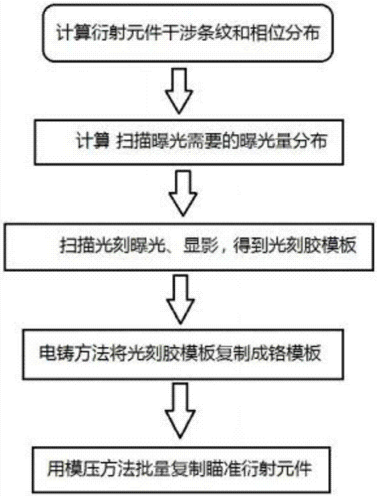
[0026] Such as figure 1 As shown, the present invention provides a method for manufacturing a diffractive optical element of a holographic sight, which includes the following steps:

[0027] S1. Calculate the fringe distribution and phase distribution required on the diffractive optical element; including: determining the working parameters of the diffractive element, and calculating the fringe distribution and the phase distribution according to the working parameters, the principle of optical interference and the principle of Fourier optics Phase distribution; the working parameters include working wavelength, reference incident light angle, and holographic reconstruction light position;

[0028] S2. Converting the fringe distribution and the phase distribution into template depth distribution and exposure distribution;

[0029] S3. According to the depth distribution of the template and the exposure amount distribution, a three-dimensional relief mechanism is fabricated on the pho...

Embodiment 2

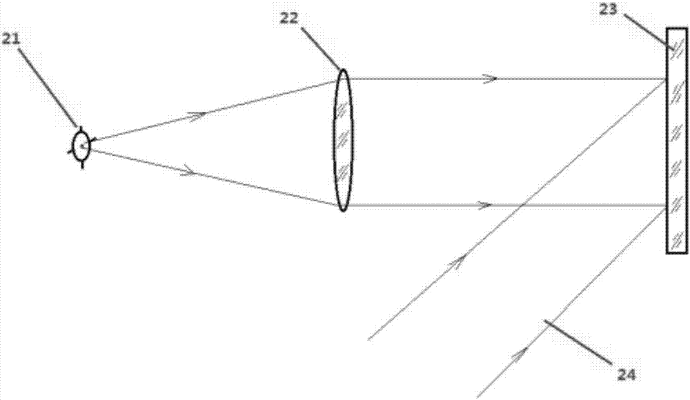
[0035] S1. The distribution and phase of fringes on the holographic aiming lens. according to figure 2 In the ideal light path shown, the aiming cross-hair image 21 is located on the focal plane of the Fourier transform lens 22, and the focal length is f. The light field distribution of the cross-hair image after passing through the lens can be expressed by the following formula:

[0036]

[0037] The angle between the parallel beam 24 and the optical axis of the lens 22 is θ (the θ angle is generally in the range of 45-60 degrees), which can be expressed as:

[0038] R(x,y)=R 0 exp(jkxsinθ)

[0039] The two light fields interfere on the holographic sight 23 to form interference fringe distribution and phase distribution, which can be expressed as:

[0040]

[0041] According to the phase distribution obtained above, combined with the refractive index of the PET film, the depth of the depression required for each point of the PET to achieve the above phase distribution can be calcula...


PUM


Abstract

The invention provides a manufacturing method of a holographic diffractive optical element. The manufacturing method comprises the following steps of calculating needed fringe distribution and phase distribution; converting the fringe distribution and the phase distribution to template depth distribution and exposure distribution; according to the template depth distribution and the exposure distribution, manufacturing a photoresist mask on a photoresist substrate; copying the photoresist mask to chromium metal to generate a surface micro-structure, and obtaining a chromium template; copying the surface micro-structure on the chromium template to a diffractive optical substrate, and obtaining the holographic diffractive optical element. The needed diffraction pattern obtained by the adoption of a computer algorithm is not influenced by actual optical element manufacturing errors, flaws, environment stray light and optical system adjusting errors; electron beam scanning or ultraviolet scanning is adopted for conducting exposure to manufacture a photoresist template. The chromium template is manufactured by the adoption of an electroforming method without complicated holographic exposure optical path, the adjusting requirements on an optical system are reduced, and the influence of environment factors is dramatically reduced.

Description

Technical field [0001] The invention relates to the technical field of sights, in particular to a method for manufacturing diffractive optical elements of a holographic sight. Background technique [0002] The optical sight has gone through several stages such as traditional optical sight, white light sight, red dot sight and holographic sight. The holographic sight uses the principle of light diffraction to provide a collimated reticle image. The center aiming point comes from the infinite parallel light, which can ensure that the aiming baseline is straight and stable. In addition, it also has a series of advantages such as high transmittance, large field of view, allowing binocular opening operation, precise aiming point, and bright reticle pattern. At present, the diffractive optical element in the holographic sight is generally manufactured by using double-beam interference light path for holographic exposure, and then undergoing a series of processes such as developing, fi...

Claims


Application Information

Patent Timeline
Patent Type & Authority Applications(China)
IPC IPC(8): G02B5/18G03H1/04
Inventor 蔡志坚鄢红日
Owner 盖伯精工(江苏)有限公司
Learn More