Pore ​​etching method of aluminum foil and method of producing etched foil

A manufacturing method and technology of corroding foil, which is applied to capacitors, circuits, electrical components, etc., can solve the problems of affecting capacitor performance, affecting capacitor shell size, increasing volume of rolls, etc., to reduce volume, improve uniformity and quantity, and ensure The effect of mechanical strength

Active Publication Date: 2018-12-25
RUYUAN YAO AUTONOMOUS COUNTY DONGYANGGUANG FORMED FOIL CO LTD
View PDF5 Cites 0 Cited by
  • Summary
  • Abstract
  • Description
  • Claims
  • Application Information

AI Technical Summary

Problems solved by technology

The most ideal way is to increase the uniformity of the corrosion pores and the uniformity of the tunnel hole development at the same time, and then increase the overall density of the pores of the aluminum foil, which can naturally increase the specific volume of the corrosion foil, but this method is technically difficult to achieve Maximum, uniformity control in the corrosion process is also a bottleneck that is difficult to break through in the development of anode foil manufacturing technology
The method of increasing the thickness of the light foil or maintaining the excess thickness of the corroded aluminum foil can increase the specific capacity to a certain extent, but because the thickness of the anode foil produced is too thick, the volume of the package will be increased when the capacitor is wound. Affect the shell number of the capacitor, and the performance of the manufactured capacitor will also be affected

Method used


Image

  • Pore ​​etching method of aluminum foil and method of producing etched foil
  • Pore ​​etching method of aluminum foil and method of producing etched foil
  • Pore ​​etching method of aluminum foil and method of producing etched foil

Examples


Embodiment 1

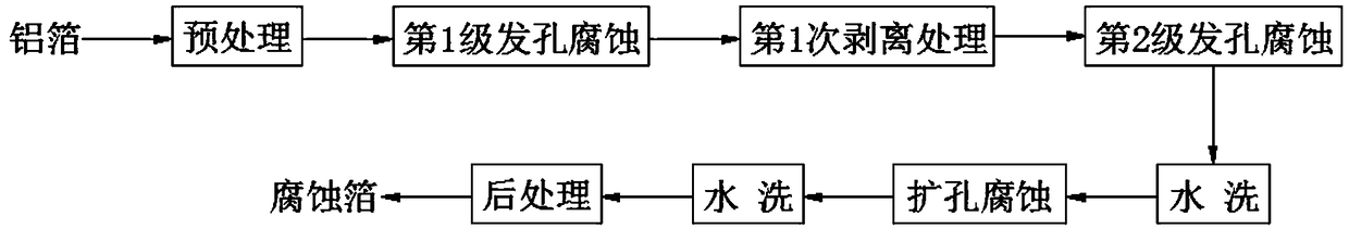
[0026] see figure 1 , which is a flow chart of the process of manufacturing the corroded foil in this embodiment, and this embodiment is specifically carried out according to the following steps:

[0027] (1) Pretreatment: Take a soft electronic aluminum foil with a purity greater than or equal to 99.99% and a thickness of 123 μm and soak it in a phosphoric acid solution with a mass fraction of 4%. The soaking temperature is 65°C and the soaking time is 60 seconds.

[0028] (2) Level 1 porosity corrosion: soak the pretreated aluminum foil in a corrosion solution containing 35% sulfuric acid and 5% hydrochloric acid by mass percentage, the soaking temperature is 75°C, and the average current density is 0.5A / cm 2 Electrolytic corrosion is carried out with a high current, and the processing time is 50 seconds.

[0029] (3) The first peeling treatment: soak the aluminum foil that has undergone the first level of porosity corrosion in a 3% fluosilicic acid solution, the soaking ...

Embodiment 2

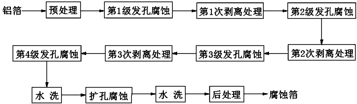
[0036] see figure 2 , which is a flow chart of the process of manufacturing the corroded foil in this embodiment, and this embodiment is specifically carried out according to the following steps:

[0037] (1) Pretreatment: Take a soft electronic aluminum foil with a purity greater than or equal to 99.99% and a thickness of 123 μm and soak it in a phosphoric acid solution with a mass fraction of 5%. The soaking temperature is 65°C and the soaking time is 60 seconds.

[0038](2) Level 1 porosity corrosion: soak the pretreated aluminum foil in a corrosion solution containing 33% sulfuric acid and 4.5% hydrochloric acid by mass percentage, the soaking temperature is 74.5°C, and the average current density is 0.53A / cm 2 Electrolytic corrosion was carried out with a high current, and the treatment time was 40 seconds.

[0039] (3) The first peeling treatment: soak the aluminum foil that has undergone the first level of porosity corrosion in a 2.5% fluorosilicic acid solution at ...

Embodiment 3

[0048] see image 3 , which is a flow chart of the process of manufacturing the corroded foil in this embodiment, and this embodiment is specifically carried out according to the following steps:

[0049] (1) Pretreatment: Take a soft electronic aluminum foil with a purity greater than or equal to 99.99% and a thickness of 123 μm and soak it in a phosphoric acid solution with a mass fraction of 2%. The soaking temperature is 75°C and the soaking time is 60 seconds.

[0050] (2) Level 1 porosity corrosion: soak the pretreated aluminum foil in a corrosion solution containing 32% sulfuric acid and 4.2% hydrochloric acid by mass percentage, the soaking temperature is 74°C, and the average current density is 0.55A / cm 2 Electrolytic corrosion is carried out with a high current, and the processing time is 30 seconds.

[0051] (3) The first peeling treatment: soak the aluminum foil that has undergone the first level of porosity corrosion in a 2% fluorosilicic acid solution, the soa...


PUM

PropertyMeasurementUnit
quality scoreaaaaaaaaaa

Abstract

The invention relates to a pitting corrosion method for aluminum foil. The pitting corrosion method comprises N stages of pitting corrosion treatment and N-1 times of stripping treatment, wherein N is an integer which is equal to or greater than two. Stripping treatment is conducted once between every two stages of pitting corrosion treatment. Each stage of pitting corrosion treatment comprises the steps that the aluminum foil is placed in corrosive liquid containing sulfuric acid and hydrochloric acid so as to be soaked, and currents are applied for electrolytic corrosion at the same time. Each time of stripping treatment comprises the step that the aluminum foil is placed in a fluosilicic acid solution so as to be soaked. The invention further relates to a preparation method of etched foil. The preparation method comprises the steps of pretreatment, pitting corrosion, hole-expanding corrosion and aftertreatment, and the step of pitting corrosion is conducted through the pitting corrosion method. By adoption of the pitting corrosion method, the uniformity and number of pits of the aluminum foil can be improved, and thus the specific volume of the etched foil is improved; and the pitting corrosion method has the advantages that the pitting corrosion method is easy to realize, the thickness is decreased, and the size of a capacitor can be reduced easily.

Description

technical field [0001] The present invention relates to a manufacturing process of aluminum foil for electrolytic capacitors, in particular to a method for corroding pores of aluminum foil and a manufacturing method for corroded foil. Background technique [0002] Aluminum electrolytic capacitors are energy storage components widely used in the electronic and electrical industries, and the anode foil for aluminum electrolytic capacitors is an important raw material. The structural characteristics of the anode foil determine the electrical properties of aluminum electrolytic capacitors. With the rapid development of electronic information technology and the birth of new complete machines, the demand for miniaturized, chip-type, medium-high voltage and large-capacity electrolytic containers continues to grow, which puts forward higher requirements for the specific volume of the anode foil. [0003] Anode foil refers to the aluminum foil used as an anode in electrolytic capacit...

Claims


Application Information

Patent Timeline
Patent Type & Authority Patents(China)
IPC IPC(8): C25F3/04H01G9/055
CPCC25F3/04H01G9/055
Inventor 陈锦雄罗向军汪启桥吕根品
Owner RUYUAN YAO AUTONOMOUS COUNTY DONGYANGGUANG FORMED FOIL CO LTD
Why Eureka
Try Eureka