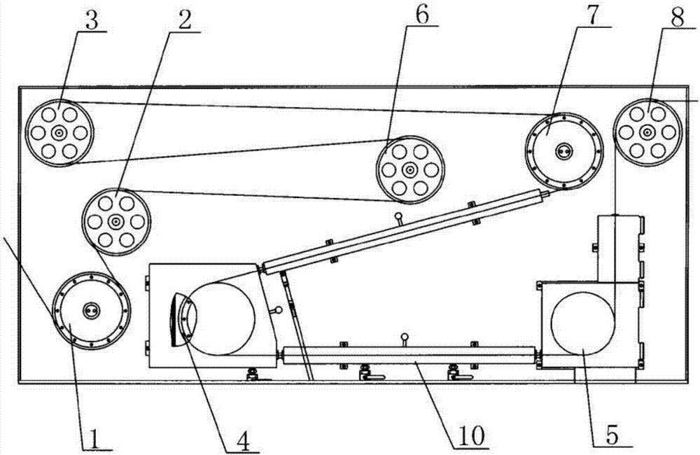
Novel material large-diameter annealing machine
A new material, large diameter technology, applied in the furnace type, coating, furnace and other directions, can solve the problems of reducing the insulation level of insulating parts, carbon brush wheel heating, low annealing current, etc., to achieve full and uniform heating and cooling, increase the use of Longevity and the effect of guaranteeing the insulation level
- Summary
- Abstract
- Description
- Claims
- Application Information
AI Technical Summary
Problems solved by technology
Method used
Image


Examples
Embodiment 1
[0024] The high-temperature-resistant and wear-resistant coating is composed of material A and material B in a ratio of 70:30 by weight, wherein:
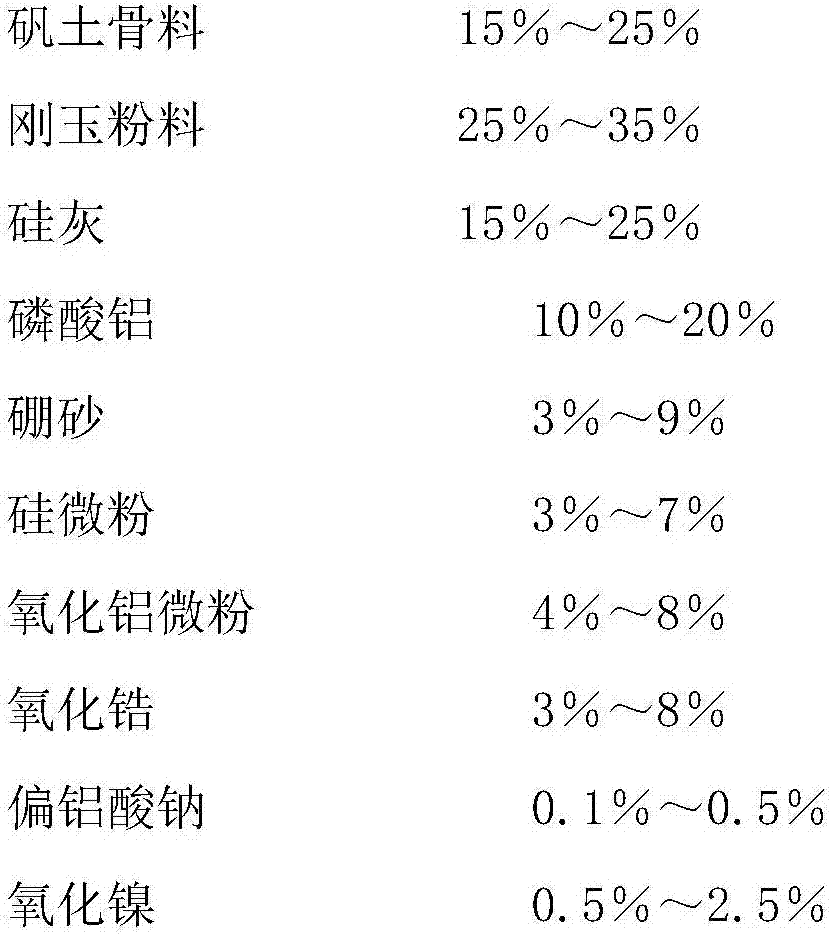
[0025] The proportion by weight of each component of material A is 20% of bauxite bone, 25% of corundum powder, 22.9% of silica fume, 15% of aluminum phosphate, 4% of borax, 5% of silica powder, 4% of alumina powder, and 3% of zirconia. %, sodium metaaluminate 0.1%, nickel oxide 1%;
[0026] The proportion by weight of each component of material B is 75% of phosphoric acid, 9% of aluminum hydroxide, 7% of sodium citrate, 8% of ethanol, and 1% of fused calcium chromate. Among them, the concentration of phosphoric acid is 85%.
[0027] The preparation method of the high-temperature-resistant and wear-resistant coating is to weigh the components of the first material according to the weight percentage ratio: alumina aggregate, corundum powder, silica fume, aluminum phosphate, borax, silicon micropowder, alumina micropowder, zirconia ...
PUM
| Property | Measurement | Unit |
|---|---|---|
| length | aaaaa | aaaaa |
| diameter | aaaaa | aaaaa |
Abstract
Description
Claims
Application Information
 - R&D
- Intellectual Property
- Life Sciences
- Materials
- Tech Scout
- Unparalleled Data Quality
- Higher Quality Content
- 60% Fewer Hallucinations
Browse by: Latest US Patents, China's latest patents, Technical Efficacy Thesaurus, Application Domain, Technology Topic, Popular Technical Reports.
© 2025 PatSnap. All rights reserved.Legal|Privacy policy|Modern Slavery Act Transparency Statement|Sitemap|About US| Contact US: help@patsnap.com