
Systems and methods for cooling electronic equipment in a data center

A technology for data center cooling and electronic equipment, which is applied to electrical equipment structural parts, heat exchange equipment, lighting and heating equipment, etc., and can solve problems such as difficult-to-cool areas, insufficient cooling, and unavailability.

Active Publication Date: 2019-11-05
GOOGLE LLC
View PDF5 Cites 0 Cited by
  • Summary
  • Abstract
  • Description
  • Claims
  • Application Information

AI Technical Summary

Problems solved by technology

In some cases, one or more components or devices on a server tray may be located in areas of the tray that are difficult to cool; for example, areas where forced convection is less effective or unavailable
[0004] Insufficient and / or insufficient cooling may result in one or more electronic devices on the tray failing due to the temperature of the device exceeding the maximum rated temperature
While some redundancy may be built into computer data centers, server racks, or even individual trays, equipment failure due to overheating can still be extremely costly in speed, efficiency, and expense

Method used


Image

  • Systems and methods for cooling electronic equipment in a data center
  • Systems and methods for cooling electronic equipment in a data center
  • Systems and methods for cooling electronic equipment in a data center

Examples


Embodiment Construction

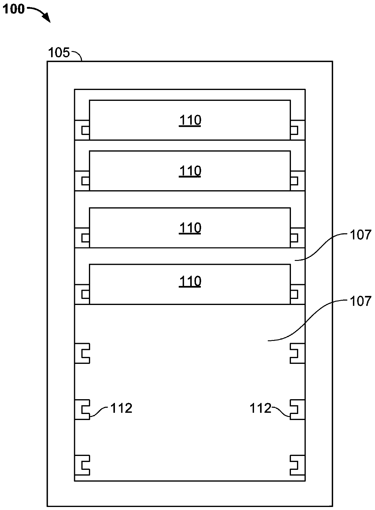
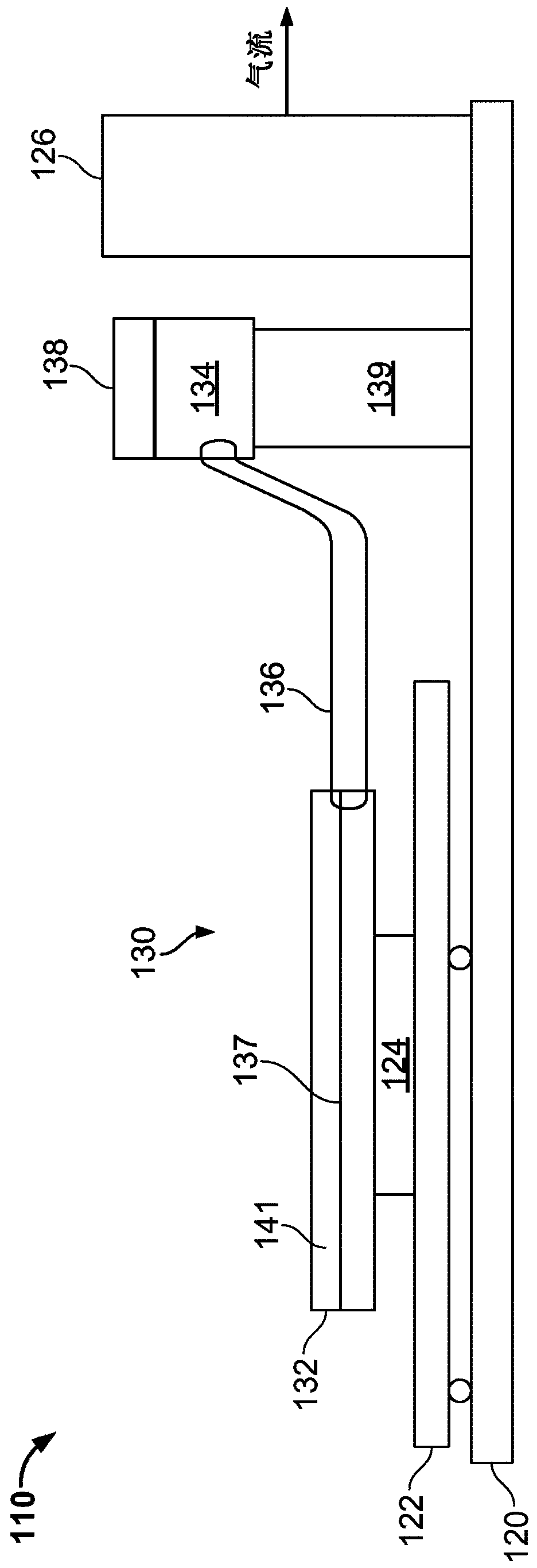
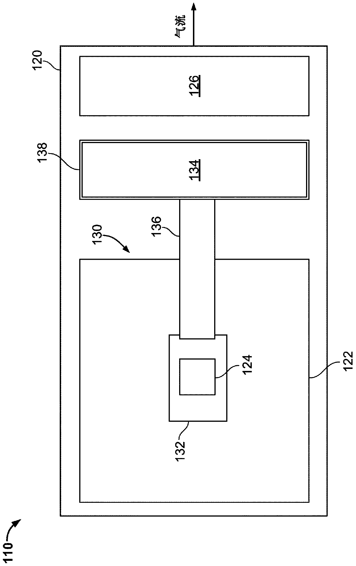
[0039] This document discloses a modular heat sink operable to cool one or more electronic heat generating devices, such as devices located on server rack subassemblies (eg, server trays) in a data center. In some embodiments, modular heat sinks can provide hot spot cooling and three-dimensional distribution of heat generated by these devices to handle high heat fluxes. In some embodiments, a modular heat sink according to the present disclosure includes an evaporator, a transfer tube, and a condenser.

[0040]In some embodiments of a modular heat sink according to the present disclosure, the evaporator comprises a small copper block with a heat transfer surface (eg, a fin structure). The fins in the fin construction can be machined or cut, or they can be welded or brazed to the evaporator small copper block as a separate part. The fins can be plate fins or pin fins and can be coated with copper porous particles to increase evaporation rate and reduce thermal resistance. In ...


PUM


Abstract

Cooling electronic equipment in a data center is disclosed. A data center cooling system includes a modular heat sink and a working fluid. The modular heat sink includes: an evaporator configured to be in thermal contact with the heat generating electronics to receive heat from the data center heat generating electronics; a condenser coupled to the evaporator and configured to receive heat from the heat generating electronics and a plurality of delivery tubes fluidly coupling the evaporator and the condenser, at least one of the plurality of delivery tubes comprising an open end disposed in the evaporator and a closed end. The working fluid is vaporized in the evaporator upon receiving heat from the heat generating electronics, and is circulated in a vapor phase from the evaporator to the condenser and in a liquid phase from the condenser to the evaporator in the conveying member.

Description

technical field [0001] This document relates to systems and methods for providing cooling of electronic devices, such as computer server racks and related devices in computer data centers. Background technique [0002] Computer users are often concerned with the speed (eg, megahertz and gigahertz) of the computer's microprocessor. Many people forget that this speed often comes at a price—higher power consumption. This power dissipation also generates heat. This is because by simple laws of physics, all energy has to go somewhere, and somewhere it ends up being converted to heat. A pair of microprocessors mounted on a single motherboard can draw several hundred watts or more. For the many computers in a large data center, this number needs to be multiplied by the thousands (or tens of thousands) to easily understand the amount of heat that can be generated. The impact of power consumed by critical loads in a data center is often exacerbated when incorporating all the auxi...

Claims


Application Information

Patent Timeline
Patent Type & Authority Patents(China)
IPC IPC(8): H05K7/20
CPCH05K7/20809F28D15/0266F28D15/0275F28D15/04F28D15/046F28F3/048F28F13/187F28F21/085G06F1/20G06F2200/201H01L23/427H05K7/20336F28F3/04F28F21/089F28F23/00H05K7/20309H05K7/20318H05K7/20327H05K7/20409
Inventor 苏海利·法尔斯契安伊马德·萨马迪亚尼
Owner GOOGLE LLC
Learn More