
Spray head of 3D printer

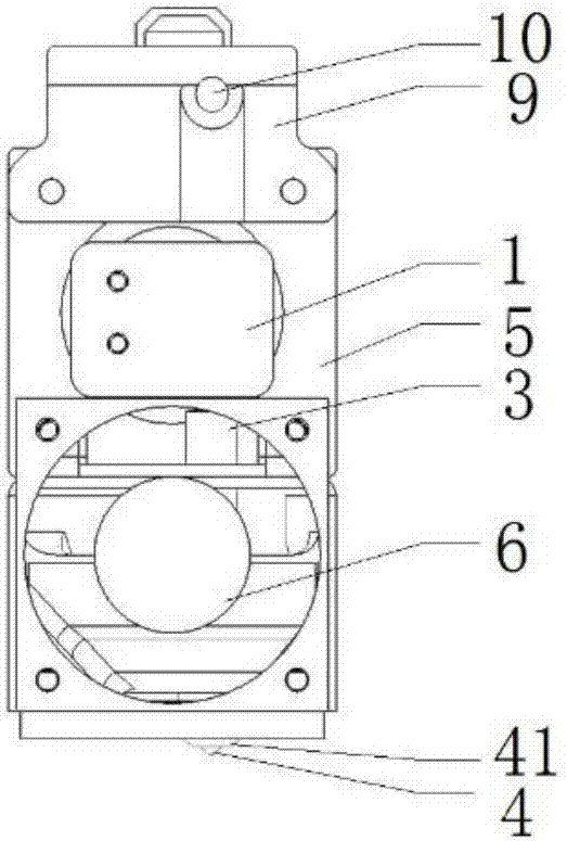
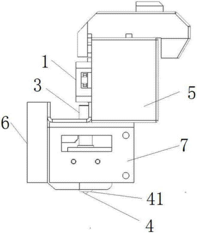
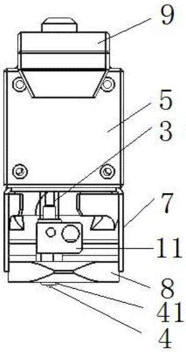
A 3D printer and nozzle technology, applied in the field of 3D printing, can solve the problems of blocked transmission of consumables, smaller contact area, soft consumables, etc., to ensure smooth wire feeding, control heat conduction, and easy to use.

Pending Publication Date: 2017-10-13
WUXI TIERTIME TECH CO LTD
View PDF4 Cites 2 Cited by
  • Summary
  • Abstract
  • Description
  • Claims
  • Application Information

AI Technical Summary

Problems solved by technology

[0003] In the 3D printing of fused deposition modeling technology, the consumables are transported through the feeding structure and melted in the liquefier. The temperature of the liquefier will be transmitted upward along the feeding structure and the consumables. The heated consumables become soft and even deformed, which seriously affects the transmission of consumables.
In the existing technology, the feeding structure is mostly the cooperation of the driving wheel and the driven wheel, and a certain distance is set in the middle. This distance is directly determined by the diameter of the consumables. Generally, the printing consumables with a diameter of 1.75mm are used in the market. Generally, there are two situations. In the first situation, the high temperature extends to the position of the feeding structure, and the consumables are directly heated and softened, or even stretched. When the consumables pass through the distance between the driving wheel and the driven wheel, the contact area between the driving wheel and the driven wheel of the feeding structure and the consumables will be caused. In the second case, the high temperature extends to the lower part of the feeding structure and above the liquefier, and the consumables become softer, but the upper feeding force remains the same. In the process of 3D printing, the consumables will be drawn back according to the printing requirements. When the softened consumables do not enter the liquefier, when the retraction design is performed at the same time, the feeding structure cannot withdraw the softened consumables in time, and then If it is fed, the first situation will appear, which will affect the normal printing
[0004] In view of the above problems, the driving wheel and driven wheel of the feeding structure in the prior art generally use the cooperation of gears and pressure wheels, and the consumables are directly sent into the liquefier from the feeding structure, and an integrated transmission channel is provided at the upper end of the liquefier. 1 cm transmission channel, and set up heat sinks to reduce the influence of consumables caused by the upward transmission of the temperature of the liquefier, resulting in the obstruction of consumables transmission; or further design a new feeding structure, using adjustable pressure wheel spacing and other designs to increase flexibility The components control the pressure rollers, thereby controlling the spacing, which can further increase the feeding force. There are many auxiliary parts in this kind of structure, which are relatively complicated. Although the fault tolerance rate of consumables is improved, it also increases the uncertainty of the structure and increases the possibility of problems. possibility

Method used


Image

  • Spray head of 3D printer
  • Spray head of 3D printer
  • Spray head of 3D printer

Examples


Embodiment 2

[0033] In this embodiment, the material of the transmission channel is specifically selected as polyether ether ketone, its melting point is 334°C, heat distortion temperature is 315°C, and the friction coefficient is 0.3; the inner layer of the transmission channel is polytetrafluoroethylene: the friction coefficient is not greater than 0.1; The material of the mouth guard is polyetheretherketone, which has a melting point of 334°C, a heat distortion temperature of 315°C, and a surface tension of γ S Be 34.53mN / m; Other structure is the same as embodiment 1.

[0034] The working process of the nozzle of the 3D printer is:

[0035] Printing starts, the motor works, the fan works, the heating component works, the consumables enter the feeding structure from the wire inlet of the auxiliary clamping part, the driving wheel and the driven wheel of the feeding structure convey the consumables downward, enter the channel, and then convey to the liquefier In the liquefier, the heati...


PUM

PropertyMeasurementUnit
Melting pointaaaaaaaaaa
Heat distortion temperatureaaaaaaaaaa
Surface tensionaaaaaaaaaa

Abstract

The invention relates to the technical field of 3D printing, in particular to a spray head of a 3D printer. The spray head comprises a feeding structure, a liquefier and a shower nozzle, wherein the feeding structure is connected with the liquefier by means of a transfer passage; the lower part of the liquefier is connectd with the shower nozzle; and a protection nozzle sleeves the shower nozzle. Through adoption of the design that the feeding structure is connected with the liquefier by means of the transfer passage, heat conduction is effectively controlled, and smooth wire feeding is ensured; the spray head is simple in structure and convenient to use; and by combination between the protection nozzle and the shower nozzle, after the shower nozzle works for a long time for printing, the condition that materials are stuck and carbonized on the spray head is effectively reduced.

Description

technical field [0001] The invention relates to the technical field of 3D printing, in particular to a spray head of a 3D printer. Background technique [0002] 3D printing technology has developed rapidly because of its many advantages over the existing subtractive processing technology. This patent relates to the field of 3D printing based on fused deposition modeling technology. The solid 3D printing consumables are heated to a molten state through the nozzle. The material is extruded through the nozzle, and the layers are accumulated and printed, and finally the printed model is formed. [0003] In the 3D printing of fused deposition modeling technology, the consumables are transported through the feeding structure and melted in the liquefier. The temperature of the liquefier will be transmitted upward along the feeding structure and the consumables. The heated consumables become soft and even deformed, which seriously affects the transmission of consumables. . In the...

Claims


Application Information

Patent Timeline
IPC IPC(8): B29C64/118B29C64/209B29C64/321B29C64/295B33Y30/00B33Y40/00
CPCB29C31/00B33Y30/00B33Y40/00Y02P10/25
Inventor 郭戈唐果林孙志雄高明希
Owner WUXI TIERTIME TECH CO LTD
Learn More