Trickle vent

a technology of trickle vents and vents, applied in ventilation systems, lighting and heating apparatus, heating types, etc., can solve the problems of mass transportation being almost universally noisy, industrial buildings and complexes will almost always have very noisy areas, and modern buildings are so air tight, so as to reduce tooling and production costs, and the effect of minimal sound and thermal coupling between

Inactive Publication Date: 2009-02-17
ST CLOUD WINDOW
View PDF42 Cites 0 Cited by
  • Summary
  • Abstract
  • Description
  • Claims
  • Application Information

AI Technical Summary

Benefits of technology

[0012]Exemplary embodiments of the present invention solve inadequacies of the prior art by providing a combination of linear or continuous acoustic paths and air paths that diverge from the linear acoustic paths by abrupt directional changes midway along the acoustic paths. Each acoustic path terminates in an acoustic dampening tube which reduces the transmission of acoustic energy through the adjacent air path. By fabricating the acoustic and air paths from PVC or similar plastic tubing, thermal coupling and acoustic coupling through the tubing is minimal.
[0013]In a first manifestation, the invention is an air vent coupling a first building-enclosed space to a second space primarily isolated from the first building-enclosed space for air movement therebetween, while simultaneously limiting a transmission of sound and thermal energy through the air vent. A first support channel is provided which mechanically houses at least some portion of the air vent components in proper spacing relative to a building opening. A vent control is coupled to the first building-enclosed space and has an actuator which allows an occupant of the first building space to open or restrict air movement between the first building-enclosed space through the first support channel to the second space. A first segment of pipe couples air passing through the vent control to a first junction between first and second termini of a first acoustic pathway. The first acoustic pathway extends in two opposed directions from the first junction, at least immediately adjacent to the junction, and thereby defines an axis of the first acoustic pathway adjacent to the first junction. The first segment of pipe adjacent the junction is angularly offset from the axis of the first acoustic pathway. The first acoustic pathway extends in a first direction from the first junction to the first terminus and primarily blocks air from passing therethrough. The first acoustic pathway extends in a second direction opposed to the first direction to the second terminus and couples air passing through the first segment of pipe to the second space. At least one of the first segment of pipe and the acoustic pathway comprise plastic pipe, to simultaneously dampen acoustic energy and restrict thermal conduction through the pipe.
[0014]In a second manifestation, the invention is a building vent coupling a first fluid region to a second fluid region for fluid transmission therebetween, while simultaneously reducing a transmission of sound. The building vent has a ventilation gaseous exchange path formed of tubing. At least one junction connects more than two segments of tubing. At least one path of connected tubing couples the junction to the first fluid region. At least one path of connected tubing couples the junction to the second fluid region. At least one path of connected tubing extends from the junction to an acoustic terminus and has a length effective to reduce the transmission of at least one frequency of sound passing through the junction between the first and second fluid regions.
[0015]In a third manifestation, the invention is a vent coupling air within an enclosed building space to a second air space external to the enclosed building space for fluid transmission therebetween while simultaneously reducing a transmission of sound between the enclosed building space and the second air space. A first hollow support channel has an opening passing through a wall from an exterior of the first support channel to an interior thereof. A vent control is coupled through the first hollow support channel opening to allow a person within the enclosed building space to control an amount of fluid transmission. A first segment of plastic pipe is coupled with the vent control and coupled with a first one of at least two plastic pipe T-joints. A second segment of plastic pipe extends from the first one of the at least two plastic pipe T-joints perpendicular to the first segment and terminates at a pipe cap. The first one of the two plastic pipe T-joints is joined to a second one of the two plastic pipe T-joints by a third segment of plastic pipe. The third segment extends along a common longitudinal axis with the second segment and perpendicular to the first segment, and also passes through a wall of the first support channel from an interior to an exterior thereof, and passes through a wall of a second support channel from an exterior thereof to an interior. A fourth segment of plastic pipe extends from the second one of the at least two plastic pipe T-joints perpendicular to the third segment and terminates at a pipe cap. A fifth segment of plastic pipe extends from the second one of the at least two plastic pipe T-joints along a common longitudinal axis with the fourth segment and perpendicular to the third segment, and is coupled with the second air space.OBJECTS OF THE INVENTION
[0016]A first object of the invention is to provide a vent which may be used to controllably vent the interior of a generally enclosed space to the exterior, while providing minimal sound and thermal coupling therebetween. A second object of the invention is to provide such a vent in an existing passageway through a wall separating the interior from the exterior. Another object of the present invention is to incorporate standard vent closures and commonly manufactured components wherever possible, to reduce tooling and production costs. A further object of the invention is to enable fabrication to varying window sizes using the same aforementioned standard and commonly manufactured components. Yet another object of the present invention is to enable acoustic tuning of a vent to meet the needs for a specific application, while achieving the remaining objectives.

Problems solved by technology

Similarly, industrial buildings and complexes will almost always have very noisy areas such as semi-truck or rail loading docks, manufacturing areas housing loud equipment such as punch presses, grinders, lathes and other fabricating equipment, and other very noisy areas which may be located immediately adjacent to or nearby areas requiring relative sound isolation therefrom, including offices lunch rooms and other areas.
Unfortunately, mass transportation is almost universally noisy.
However, modern buildings have become so air-tight that necessary movement of air is not always provided for.
Similarly, the opening or closing of a swinging door to an otherwise sealed office or room will result in significant pressure increases or decreases within the office space.
Yet, to vent the office space will undesirably couple the space to adjacent, potentially much more noisy environments.
Unfortunately, window vents which rely upon an extrusion or a single solid structure may then couple sounds or even self-oscillate or ring upon application of sounds thereto.
Finally, window vents of the prior art also tend not to factor in or provide for the desirable thermal insulation which is desired by most modern buildings.

Method used


Image

  • Trickle vent
  • Trickle vent
  • Trickle vent

Examples


Embodiment Construction

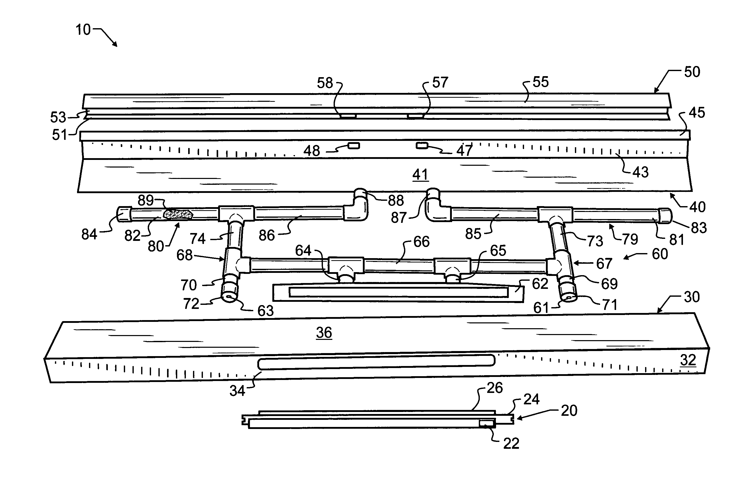
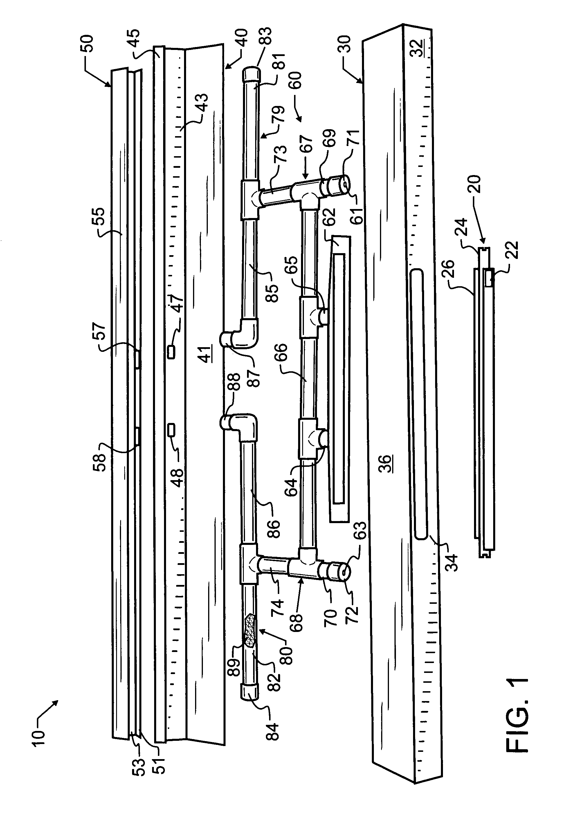
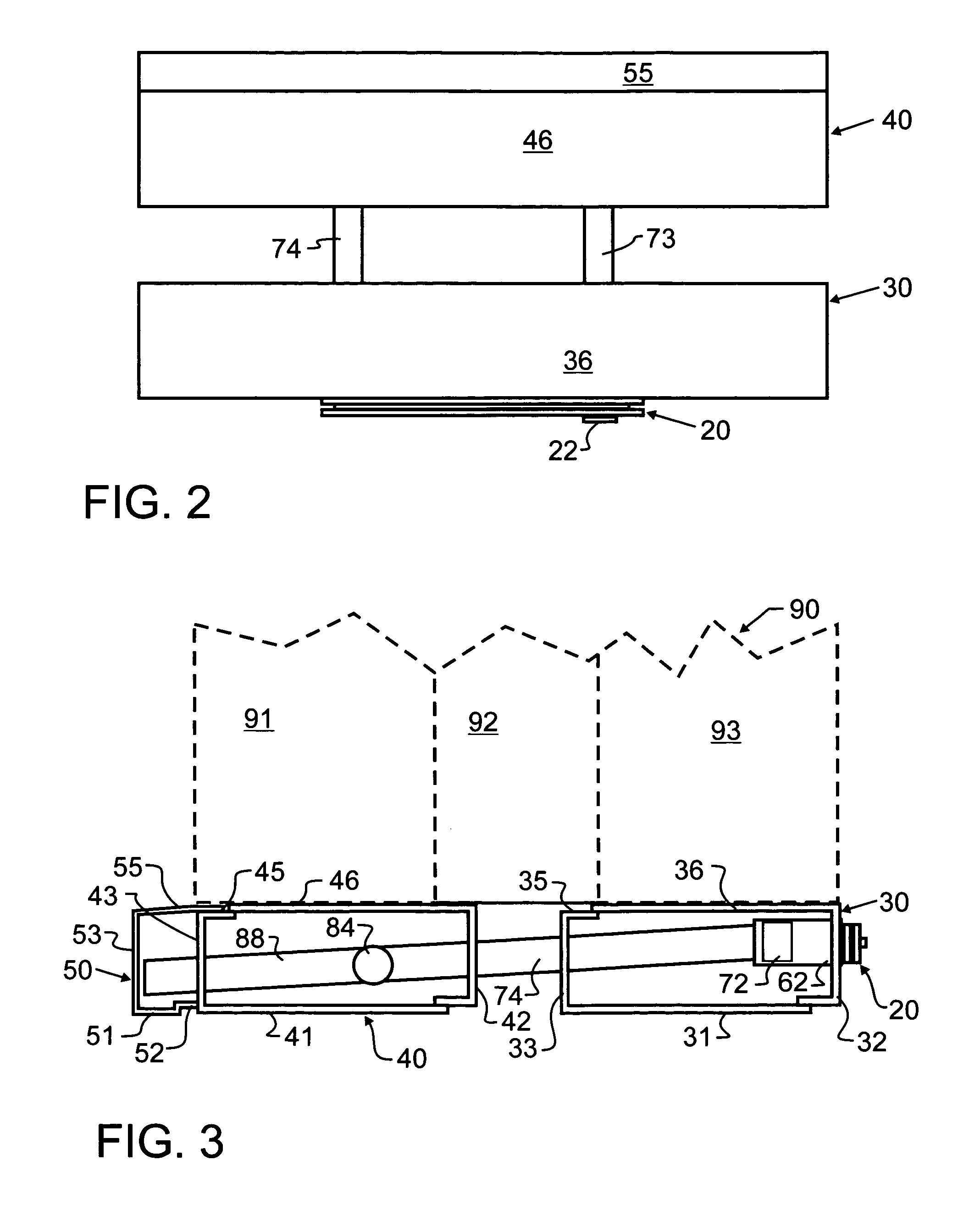
[0021]Manifested in the preferred embodiment, the present invention provides a trickle vent which couples air from one space with another, while not significantly coupling either sound or thermal energy therebetween. The preferred embodiment trickle vent 10 comprises five major components. These include a vent control 20, first structural housing 30, second structural housing 40, exterior cover 50, and sound and thermally dampening conduit 60.

[0022]Vent control 20 in the preferred embodiment is a commercially available vent control such as is illustrated for exemplary purposes in one or more of the following U.S. Pat. Nos. 4,727,797; 4,736,677; 5,244,434; 5,344,366; 5,518,452; 5,558,574; 5,702,297; 5,746,654; 5,769,706; 6,048,266; 6,558,247; and 6,648,750; the relevant teachings of each which are incorporated herein by reference. While such vent control is preferred, owing to the ready availability and added capability provided therewith, it will be recognized by those skilled in th...


PUM


Abstract

A trickle vent such as might be used in association with commercial windows is formed from PVC tubing in two convoluted paths. One or more expansion chambers are provided at turns or directional changes within the tubing which reduce or eliminate noise transmission through the vent. Where a plurality of expansion chambers are used, each chamber may be of different length to dampen a different portion of the acoustic spectrum. In a preferred embodiment, the expansion chambers are filled with an acoustic-type foam, and the ends are not completely sealed. The tubing preferably bridges two extrusions that form a supporting housing for the vent, and by using two separate extrusions bridged by the tubing, both thermal and acoustic isolation are maintained.

Description

BACKGROUND OF THE INVENTION[0001]1. Field of the Invention[0002]This invention pertains generally to ventilation for static structures, and more particularly to a trickle vent such as may be used in association with a window to provide requisite pressure equalization and the like. In a most preferred embodiment, the invention provides the desired ventilation while simultaneously inhibiting acoustic and thermal transmission.[0003]2. Description of the Related Art[0004]Shelter is considered to be a basic necessity, ranking closely in importance to food and water. While man has sought out and obtained shelter since the dawn of time, the actual embodiment of this shelter has changed over time to better fit the needs of a particular environment, and is constructed using the tools and knowledge that mankind has accumulated.[0005]Of particular interest to the present invention is the modern building structure, particularly that which is most commonly found in industrial and commercial sett...

Claims


Application Information

Patent Timeline
Patent Type & Authority Patents(United States)
IPC IPC(8): F24F7/00E06B7/03F24F13/18
CPCE06B7/10F24F13/18Y10S454/906
Inventor CASEY MAHON, S. A.
Owner ST CLOUD WINDOW
Why Eureka
Try Eureka