
Preparation process for plate roller for printing

A technology for preparation process and version roller, which is applied in the field of preparation process of printing version roller, can solve the problems of reducing surface smoothness difference and large surface smoothness difference, and achieves small surface roughness, small difference, and reduced times The effect of defective product rate

Active Publication Date: 2017-08-08
ZIBO YUNCHENG PLATE MAKING
View PDF9 Cites 7 Cited by
  • Summary
  • Abstract
  • Description
  • Claims
  • Application Information

AI Technical Summary

Problems solved by technology

[0004] The purpose of the present invention is to provide a preparation process for printing plate rolls, which solves the problem of large differences in surface smoothness at different positions on the same plate roll, and has the advantage of reducing the difference in surface smoothness at different positions on the same plate roll

Method used


Image

  • Preparation process for plate roller for printing

Examples

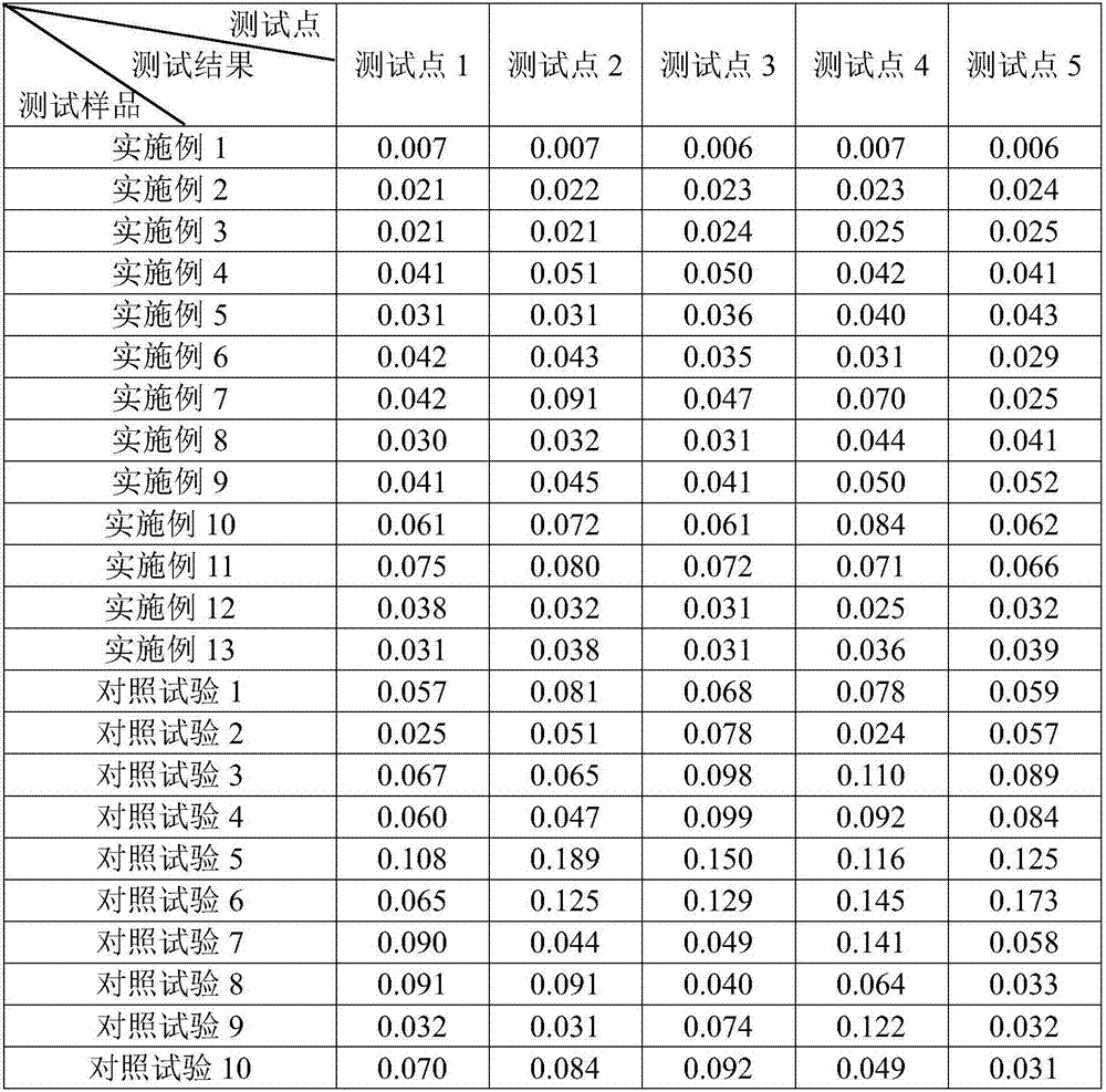

Embodiment 1

[0023] Embodiment 1: a kind of preparation technology of plate roller for printing comprises the following steps:

[0024] (1) Production of plate roller base: it is processed by seamless steel pipe;

[0025] Among them, in terms of mass percentage, the formula of seamless steel pipe is: C: 0.01%; Si: 0.35%; Mn: 0.02%; S: 0.005%; P: 0.005%; Cr: 15.50%; : 0.48%; N: 0.01%; Ti: 0.02%; the balance is Fe and unavoidable impurities;

[0026] (2) Copper plating treatment on the base of the version roller: place the base of the version roller in an electroplating tank equipped with a copper plating solution for copper plating, and the thickness of the copper layer plated is 15-18 μm;

[0027] Among them, the copper plating solution includes 5g / l of CuSO 4 , 0.4g / l Na 2 SO 3 , 0.3g / l complexing agent, 0.2g / l NaCl and 0.02g / l PVA, and the pH of the copper plating solution is 12.0-13.0;

[0028] (3) Surface treatment of plate roller after copper plating: grinding the copper surface;...

Embodiment 2

[0034] Example 2: A preparation process of a printing plate roller, the difference from Example 1 is that the formula of the seamless steel pipe is: C: 0.01wt%; Si: 0.40wt%; Mn: 0.02wt%; S P: 0.005wt%; Cr: 15.00wt%; Ni: 8.50wt%; Cu: 0.45wt%; N: 0.01wt%; Ti: 0.03wt%; the balance is Fe and unavoidable impurities .

Embodiment 3

[0035] Example 3: A preparation process of a printing plate roller, the difference from Example 1 is that the formula of the seamless steel pipe is: C: 0.02wt%; Si: 0.45wt%; Mn: 0.03wt%; S P: 0.01wt%; Cr: 16.00wt%; Ni: 9.00wt%; Cu: 0.50wt%; N: 0.02wt%; Ti: 0.04wt%; the balance is Fe and unavoidable impurities .


PUM

PropertyMeasurementUnit
thicknessaaaaaaaaaa
thicknessaaaaaaaaaa

Abstract

The invention discloses a preparation process for a plate roller for printing. The process comprises the following steps that (1) manufacturing of a plate roller base body: the plate roller base body is manufactured from a specific formula of seamless steel tube; (2) copper plating treatment of the plate roller base body: the plate roller base body is subjected to copper plating in a plating tank containing a specific copper plating solution, and the thickness of a copper layer is 12-15 microns; (3) surface treatment of the plate roller base body: the copper surface is subjected to grinding treatment; (4) gumming of the plate roller: the plate roller subjected to copper plating and surface treatment is coated with a layer of glue solution with the thickness being 0.08-0.12mm and then is aired; (5) manufacturing of a laser image, laser engraving of the plate roller and developing of the plate roller; (6) corrosion to the plate roller: the plate roller is subjected to spray-type corrosion treatment with specific corrosive liquid; (7) cleaning of the plate roller: the plate roller is subjected to spray-type cleaning with specific cleaning fluid; and (8) chromium plating of the plate roller: the plate roller is subjected to chromium plating treatment in a plating tank containing a specific chromium plating solution, the thickness of a chromium layer is 5-8 microns. The preparation process has the advantage that the difference of the surface flatness of different positions of the same plate roller is reduced.

Description

technical field [0001] The invention relates to the technique of a printing plate, in particular to a preparation process of a printing plate. Background technique [0002] Plate rolls, also known as steel rolls, are generally used for plate making. Commonly used version rollers are copper-plated on the surface of the cylinder, engraved with a gravure electronic engraving machine, and then plated with a layer of chromium. The completed plate roll is often used for printing on plastic packaging. [0003] The Chinese patent application published as CN103481638A and published on January 1, 2014 discloses a master roll for laser paper printing and its manufacturing process, which includes copper plating, encapsulation, laser engraving, corrosion, degumming and Chrome finish. In these processes, the surface of the plate roll is treated multiple times, and the degree of reaction of the plate roll is different, resulting in a large difference in the surface smoothness of differe...

Claims


Application Information

Patent Timeline
Patent Type & Authority Applications(China)
IPC IPC(8): B41C1/05B41C1/18B41N1/20B41N3/03B41N3/04B41N3/00C22C38/42C22C38/50C22C38/04C22C38/02C25D3/38C25D3/04C25D5/12G03F7/00
CPCB41C1/05B41C1/188B41N1/20B41N3/003B41N3/03B41N3/04C22C38/02C22C38/04C22C38/42C22C38/50C25D3/04C25D3/38C25D5/12G03F7/00
Inventor 吕海荣
Owner ZIBO YUNCHENG PLATE MAKING
Learn More