
Method for packaging metal coated fiber grating

A technology of fiber grating and packaging method, which is applied in the direction of mitigating undesired effects, instruments, etc., and can solve the problem of the lack of reports on metal-coated fiber grating packaging technology, the brittle working life of glue media, and the difficulty in meeting the application of spaceborne devices To achieve the effect of ensuring the consistency of the process, improving the radiation resistance and mechanical strength, and improving the service life

Inactive Publication Date: 2017-04-19
北京玻璃研究院有限公司
View PDF11 Cites 0 Cited by
  • Summary
  • Abstract
  • Description
  • Claims
  • Application Information

AI Technical Summary

Problems solved by technology

[0004] As an emerging material, there are few reports on metal-coated fiber grating packaging technology for satellites at home and abroad.
The traditional fiber grating packaging method mostly uses silicon rubber or epoxy resin glue to directly bond the optical fiber and the assembly material, such as the Chinese patent "High Sensitivity Temperature Sensor for Meteorology" with the publication number CN204831618U, and the publication number is CN1412530A Although the Chinese patent "Single Fiber Bragg Grating Packaging Method and Sensor for Simultaneous Measurement of Strain and Temperature Change" and the Chinese patent "Fiber Bragg Grating Packaging Structure, Temperature Sensor and Packaging Method" with the publication number CN103076110A also propose packaging in metal tubes To improve the strength of fiber gratings, it has a certain ability to resist radiation, but the materials used to bond fiber gratings and metal tubes are all rubber media such as silicone rubber or epoxy resin, and the working temperature is above -60°C. When the value is lower, the rubber medium will be brittle and the working life will be shorter, resulting in package failure, which is difficult to meet the application of spaceborne devices

Method used


Image

  • Method for packaging metal coated fiber grating
  • Method for packaging metal coated fiber grating
  • Method for packaging metal coated fiber grating

Examples


Embodiment Construction

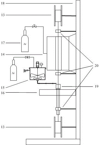
[0022] A metal-coated optical fiber grating packaging method of the present invention comprises the following steps:

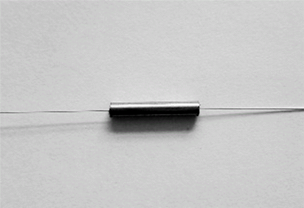
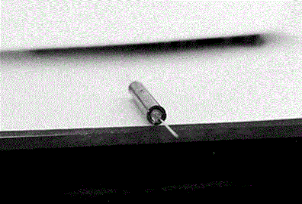
[0023] 1. Design of stainless steel tube with variable inner diameter: as shown in Figure-1, the outer diameter of the stainless steel sleeve is 1.5mm, and the inner diameter of the small diameter part in the middle is 0.18mm~0.2mm (the diameter of the metal-coated optical fiber is about 0.15mm), which is used to nest the bare fiber grating The fiber part; the inner diameter of both ends of the stainless steel sleeve is 1.3mm, which is used to fill the adhesive;

[0024] 2. Low-temperature glass frit treatment: Pour low-temperature glass frit (softening point around 380°C) and high-purity ethanol into a stirring container, stir thoroughly to obtain pasty low-temperature glass, which is used as an adhesive for optical fiber grating materials and metal tubes;

[0025] 3. Adjust the supporting metal tube (with an inner diameter greater than 0.3mm and an outer ...


PUM


Abstract

The invention discloses a method for packaging metal coated fiber grating. A sleeving-binding-forming integrated device is employed, an internal diameter-variable stainless steel pipe (1) is used as a packaging sleeve, grating bared fiber is stored in the part with small diameter (3), and a bonding agent is filled in the part with large diameter (3). Volatile liquid stirring glass powder serves as the bonding agent, and the bonding agent is filled in the two ends of a sleeve through a high pressure extrusion means, and melted and cured under inert gas protection atmosphere, thereby preventing metal oxidation. A metal sleeve is used for packing fiber grating to improve the mechanical strength and radiation-prevention capability. Glass powder is used as a bonding agent to ensure reliability and stability of the packaging effect. The working temperature range is expanded, and the working service life is prolonged.

Description

technical field [0001] The invention belongs to the field of preparation and packaging of optical fiber grating sensors, in particular to a metal-coated optical fiber grating packaging method with an aerospace application background. Background technique [0002] Fiber Bragg grating sensor is a wavelength-modulated fiber-optic sensor that obtains sensing information by modulating the wavelength of the fiber Bragg with external physical parameters. Its notable features are small size, light weight, and high precision, and it is especially suitable for the needs of aerospace products. For high-resolution optical imaging satellites, especially military reconnaissance satellites, the payload and structure of their equipment put forward higher requirements for temperature stability, uniformity and thermal deformation, not only the operating temperature range is demanding (generally required at -120 ℃~+120℃), and it also needs to solve the problem of adaptability to complex enviro...

Claims


Application Information

Patent Timeline
IPC IPC(8): G01D3/028G01D18/00
CPCG01D3/028G01D18/00
Inventor 李保群臧晓微杭利军隋宁菠徐天聪
Owner 北京玻璃研究院有限公司
Learn More