Brake pressure modulator of an electronic braking system of a utility vehicle

A commercial vehicle, brake pressure technology, applied in the direction of brake control systems, brake safety systems, brakes, etc., can solve the problems of large structural space requirements and production costs, and achieve the goals of reducing construction costs, cost advantages, and reducing costs Effect

Active Publication Date: 2017-02-22
ZF CV SYST EURO BV
View PDF5 Cites 16 Cited by
  • Summary
  • Abstract
  • Description
  • Claims
  • Application Information

AI Technical Summary

Problems solved by technology

[0003] Due to the use of spatially and structurally separate brake pressure modulators for the individual pressure regulating circuits, in the case of compressed air brake systems of the type described, a greater installation space requirement and Cost of production

Method used


Image

  • Brake pressure modulator of an electronic braking system of a utility vehicle
  • Brake pressure modulator of an electronic braking system of a utility vehicle

Examples


Embodiment Construction

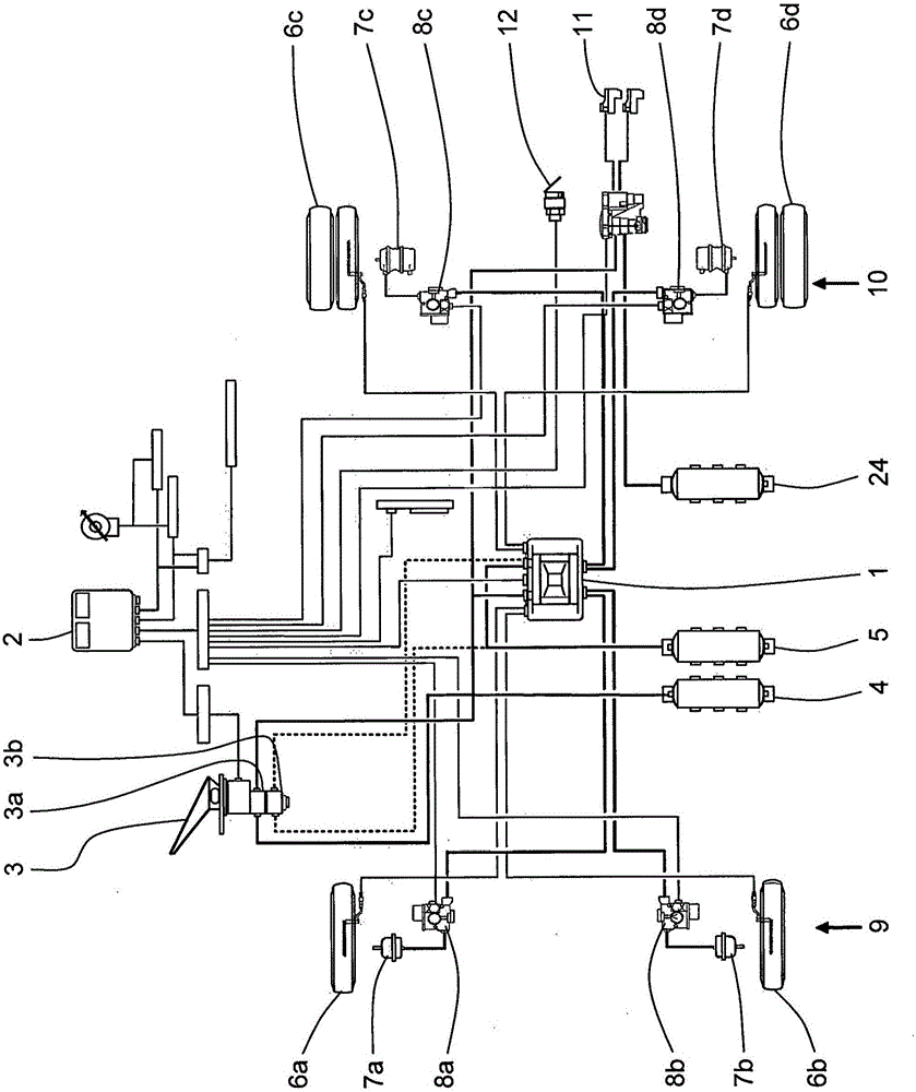
[0027] exist figure 1 In order to distinguish the pneumatic wiring and electrical wiring of components, the pneumatic connection is made with a larger line width than the electrical wiring.

[0028] figure 1 The brake system shown in has a brake pressure modulator 1 designed as a structural unit in which the hydraulic control components for the control of the two brake circuits 9 , 10 are combined. Also belonging to the brake system are the control electronics 2, the service brake parameter transmitter 3 with the first brake parameter transmitter valve 3a and optionally the second brake parameter transmitter valve 3b, the first compressed air Storage container 4 and second compressed air storage container 5, as well as a respective wheel brake 7a, 7b and a respective wheel brake modulator 8a, 8b for a wheel 6a, 6b of the front axle brake circuit 9, and a respective wheel brake modulator 8a, 8b for Each of the wheels 6a, 6b of the rear axle brake circuit 10 has a wheel brake ...


PUM


Abstract

The invention relates to a brake pressure modulator (1) of an electronic braking system of a utility vehicle, which is designed as a constructional unit with at least two pressure control circuits (13, 14). The wheels (6a, 6b, 6c, 6d) of the vehicle, which can be braked, comprise pneumatically actuated wheel brakes (7a, 7b, 7c, 7d). The pressure control circuits (13, 14) are respectively associated with a braking circuit of a vehicle axle, each pressure control circuit (13, 14) comprises a compressed air supply system (4, 5), at least one redundancy control pressure path (21), at least one ventilation path (19, 19a) and a common electronic control unit (2) being provided for the pressure control circuits (13, 14). Said pressure control circuits (13, 14) can be controlled independently from each other by means of the electronic control unit (2). According to the invention, in order to be able to produce the multi-circuit brake pressure modulator (1) in a constructionally simple manner which is also compact and economical, each pressure control circuit (13, 14) has an independent ventilation path (19, 19a) and at least one of the pressure control circuits (13, 14) has an independent redundancy control pressure path (21) and at least one other of the pressure control circuits (13, 14) comprises a device (16a) for forced venting in the event of a failure by means of the associated ventilation path (19a).

Description

technical field [0001] The invention relates to a brake pressure modulator for an electronic braking system of a commercial vehicle according to the preamble of claim 1 . Background technique [0002] The electronic braking system enables precisely metered and rapid braking of the vehicle. In this case, the output signal of the brake parameter transmitter is fed to the controller, which output signal depends on the driver's desire to decelerate. In the controller, the output signal of the brake parameter transmitter can also be modified by a driving safety system such as an anti-lock braking system, an acceleration anti-skid control or a system for a driving stability control device. The controller thus generates a control signal, which is passed to a so-called brake pressure modulator, which controls the pressure medium (compressed air in the case of commercial vehicles) via an electromagnetically actuatable valve arrangement Wheel-dependent or axle-by-axle supply to the ...

Claims


Application Information

Patent Timeline
Patent Type & Authority Applications(China)
IPC IPC(8): B60T13/68B60T17/18
CPCB60T13/683B60T17/18B60T2270/413B60T8/327B60T8/3675B60T8/94B60T13/268
Inventor 拉尔夫-卡斯滕·吕尔芬罗伯特·奥特伦巴斯特凡·雷林哈特姆特·沙普勒
Owner ZF CV SYST EURO BV
Why Eureka
Try Eureka