
Methods For Enhanced Energy Efficiency Via Systematic Hybrid Inter-Processes Integration

a technology of energy efficiency and integrated process, applied in the direction of instruments, cad techniques, analogue processes for specific applications, etc., can solve the problems of difficult control of processes, impracticality of direct inter-process integration, negative impact on the environment of the world, etc., to achieve enhanced energy efficiency, reduce greenhouse gas emissions, and enhance energy efficiency

Active Publication Date: 2013-09-05
SAUDI ARABIAN OIL CO
View PDF2 Cites 58 Cited by
  • Summary
  • Abstract
  • Description
  • Claims
  • Application Information

AI Technical Summary

Benefits of technology

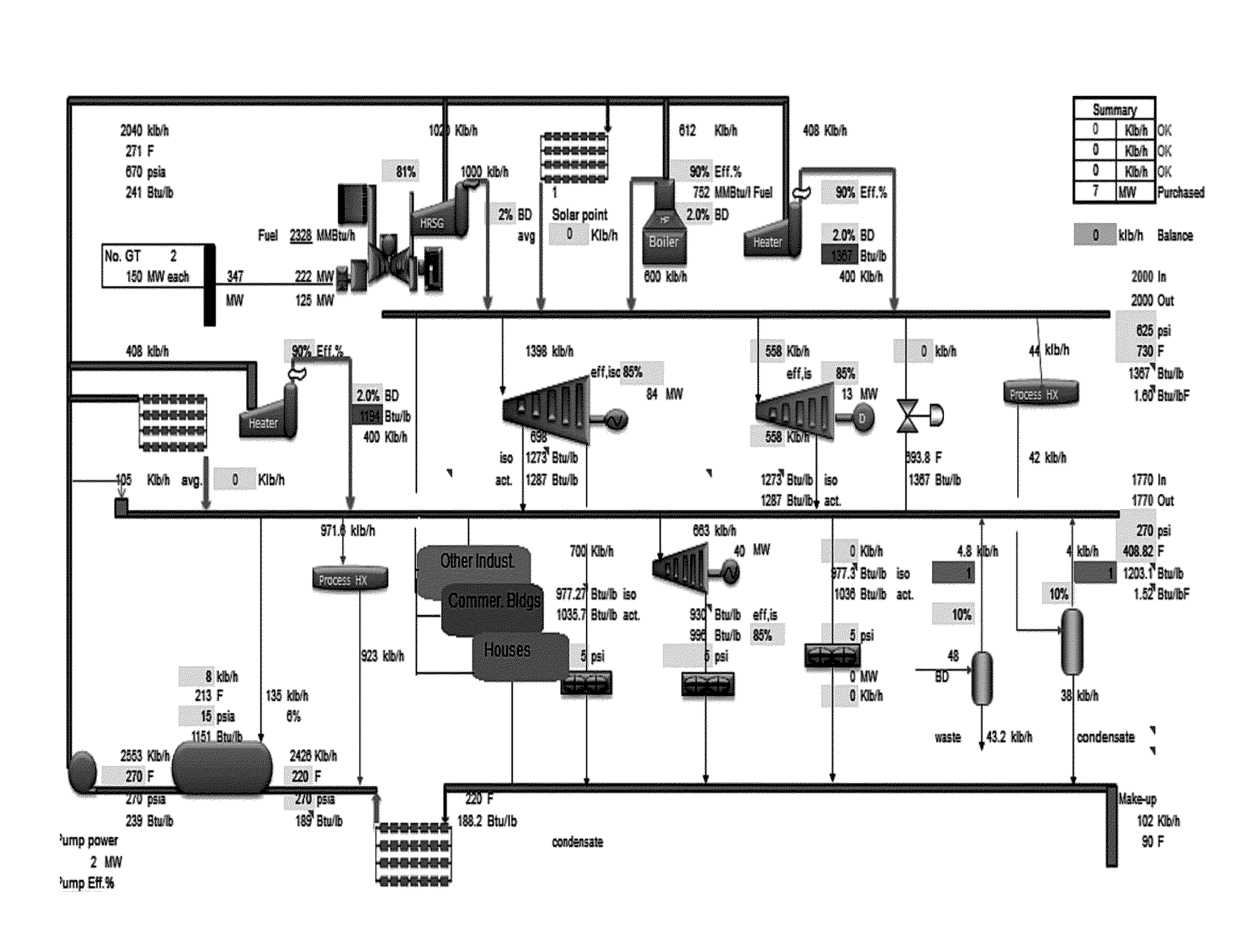
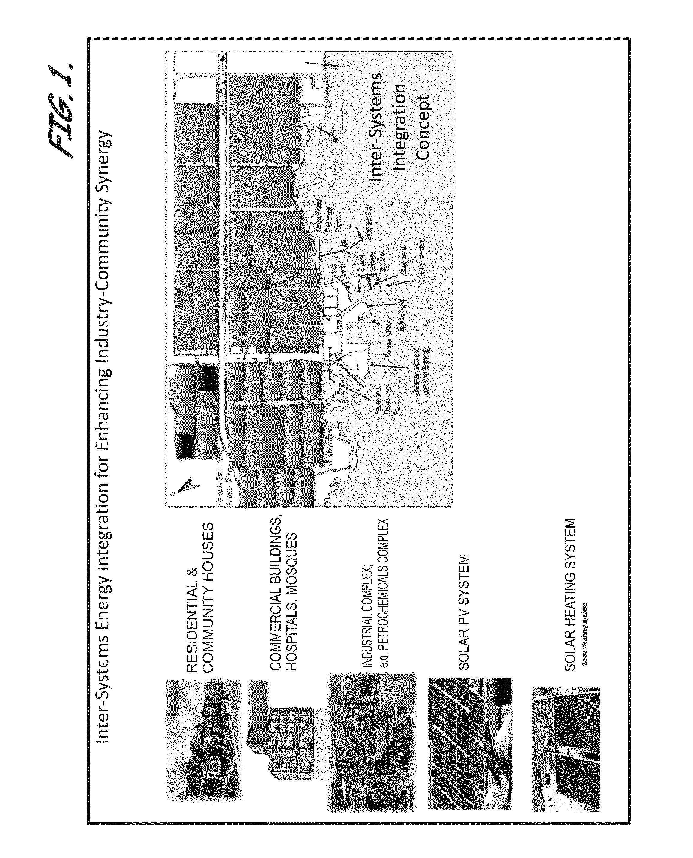
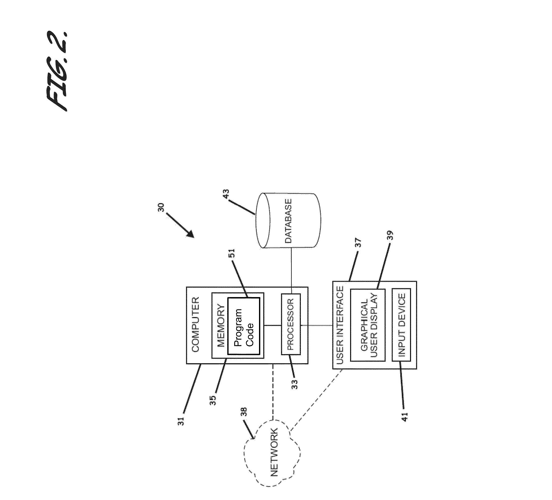
The present invention provides systems, computer-readable media, program code, and methods for energy consumption and greenhouse gas emissions reduction in mega industrial sites. The invention utilizes hybrid inter-systems energy integration techniques that can overcome current intra-systems energy integration constraints and provide better waste energy recovery. The techniques can simultaneously identify when direct and indirect inter-processes energy integration techniques are best, and can also identify when indirect inter-processes energy integration using a buffer is not recommended. The invention also provides a computer-assisted method for designing an inter-processes heat exchange system that optimizes waste heat recovery and cost allocation. Overall, the invention offers new opportunities for energy consumption and greenhouse gas emissions reduction beyond current limits.

Problems solved by technology

The majority in the world scientific communities believe that, the world's environment has been negatively affected by the global warming phenomenon due to the release of greenhouse gases (greenhouse gas) into the atmosphere.
Heat exchanger network synthesis is a multi-variable multi-dimensional optimization problem in which the total network driving distribution depends on each stream conditions and each hot stream minimum approach temperature for heat recovery.
Direct inter-processes integration has been considered by industry to be impractical.
Arguments against utilization of such integration include arguments that: the processes that would be integrated may have different start up and shut down times; the processes can work at partial loads; the processes can have seasonal changes in its conditions; capital costs of utility systems, heaters and heat exchangers network may not be reduced over that of indirect inter-processes integration due to changes in processes schedule and operation philosophy; the disturbance in one process can propagate to another one if they are integrated, making the process difficult to control; the distance-time / velocity lags affect the controllability of processes; the geographical distances among processes will result in a substantial energy cost in pumping or compression and will require capital costs associated with the piping, pumping and compression; safety might be impacted due to the travel of a fluid from one hazardous area to another; and the fear of leakage and so on, which are very common to plant engineers.
Additionally, systematic methods to handle mega sites and industrial zones for inter-processes integration are lacking and conventional mathematical programming models are not capable of handling mega size problems, where many facilities are involved in an industrial zone oversight.
Some researchers, however, have argued against using steam under certain scenarios because the generation of steam has to be accomplished at a fixed temperature levels, which may result in missed opportunities for integration, steam produced in most chemical complexes is also used to generate power, and that driving equipment and heating the steam to exactly match with process heating needs is almost impossible, and as such, usually result in venting and / or huge air cooling utilization.
Further, it is not optimal to put waste heat boilers in the process plant to recover waste heat from one end and ignore the path of this steam in the whole facility, block or industrial zone and its end point.
Additionally, in many hydrocarbon processing facilities, medium and / or high pressure steam generation or utilization not recommended for utilization in heating cold process streams, because of the fear of leakage to the hydrocarbon side and corrosion, and hence, is typically considered a forbidden match.
The researchers that favor hot oil over steam, however, have failed to mention that, in addition to the large number of hot oil circuits normally required to achieve the desired energy saving targets, the low heat transfer coefficient of the hot oil fluids result in heat exchangers requiring excessively large surface areas, more units needing to be added, and a larger number of start-up heaters and / or air coolers required per circuit, among others.
Accordingly, recognized by the inventors is the lack of a methodology that systematically identifies when the hot oil system, the steam system, or both provide the preferred solution on either the thermodynamic or economic basis.
Additionally, recognized by the inventors is that no current method adopts both direct and indirect inter-processes integration methods; no conventional method adopts the direct inter-processes integration method for mega size problems such as integrated refining, petrochemical and chemical industrial zones; and correspondingly, no conventional method adopts both direct and indirect methods using both hot oil and steam systems.
As such, the industry has a long felt, unsatisfied need for systems, computer readable media, program code, and methods to allow a user to synthesize energy recovery systems through utilization of direct and / or indirect inter-processes integration utilizing steam and / or hot oil systems, depending upon whether a decision-maker's focus is on thermodynamic or economic efficiency, or a balance between the choices.

Method used


Image

  • Methods For Enhanced Energy Efficiency Via Systematic Hybrid Inter-Processes Integration
  • Methods For Enhanced Energy Efficiency Via Systematic Hybrid Inter-Processes Integration
  • Methods For Enhanced Energy Efficiency Via Systematic Hybrid Inter-Processes Integration

Examples


Embodiment Construction

[0073]The present invention will now be described more fully hereinafter with reference to the accompanying drawings, which illustrate embodiments of the invention. This invention may, however, be embodied in many different forms and should not be construed as limited to the illustrated embodiments set forth herein. Rather, these embodiments are provided so that this disclosure will be thorough and complete, and will fully convey the scope of the invention to those skilled in the art. Like numbers refer to like elements throughout. Prime notation, if used, indicates similar elements in alternative embodiments.

TERMS

[0074]The following terms may be used throughout:

FCp: Heat capacity flowrate of a hot or cold stream

[FCp1h]: Interval Heat capacity flowrate of hot stream #1

[FCp1c]: Interval Heat capacity flowrate of cold stream #1

MM Btu / h.° F.: Million British thermal units per hour. Degree

Qc: Cooling duty required

Qh: Heating duty required

[Qc]: Interval cooling duty required

[Qh]: Interva...


PUM


Abstract

Methods for systematically providing enhanced energy efficiency of mega industrial sites and synergy with the adjacent community through advanced hybrid inter-systems energy integration targeting and solutions generation to achieve desired best levels of energy consumption and greenhouse gas emissions reduction, are provided. An exemplary method includes identifying a plurality of possible inter-processes integration energy consumption targets for a plurality of possible inter-processes energy integration combinations between a plurality of functional areas of a mega industrial site, selecting an energy-efficient inter-processes integration energy consumption target, identifying the combination of the plurality of possible inter-processes energy integration combinations providing for the energy efficient inter-processes integration energy consumption target, generating a plurality of technically viable industrial site inter-processes heat exchange system design alternatives, and identifying the technically viable industrial site inter-processes heat exchange system design substantially providing for optimal total waste heat recovery between the respective functional areas.

Description

RELATED APPLICATIONS[0001]This application is collectively a continuation-in-part of and claims priority to and the benefit of U.S. patent application Ser. No. 12 / 767,315, filed Apr. 26, 2010, titled “System, Method, and Program Product For Synthesizing Heat Exchanger Network and Identifying Optimal Topology For Future Retrofit,” which claims priority to U.S. Provisional Patent Application No. 61 / 256,754, filed Oct. 30, 2009, titled “System, Method, and Program Product for Synthesizing Non-Constrained and Constrained Heat Exchanger Networks and Identifying Optimal Topology for Future Retrofit”; U.S. patent application Ser. No. 13 / 757,467, filed on Feb. 1, 2013, titled “Methods For Simultaneous Process and Utility Systems Synthesis in Partially and Fully Decentralized Environments; and U.S. patent application Ser. No. 13 / 757,491, filed on Feb. 1, 2013, titled “Systems and Computer Programs For Simultaneous Processing Utility Systems Synthesis in Partially and Fully Decentralized Envi...

Claims


Application Information

Patent Timeline
IPC IPC(8): G06F17/50
CPCG06F2217/16G06F17/5009G06F2217/80G06F30/20G06F2111/10G06F2119/08
Inventor NOURELDIN, MAHMOUD BAHYAL-OWAIDH, MANA M.ALNUTAIFI, ABDULAZIZ M.
Owner SAUDI ARABIAN OIL CO
Learn More