
Cross-layer design techniques for interference-aware routing configuration in wireless mesh networks

Active Publication Date: 2007-09-06
CISCO TECH INC
View PDF6 Cites 55 Cited by
  • Summary
  • Abstract
  • Description
  • Claims
  • Application Information

AI Technical Summary

Benefits of technology

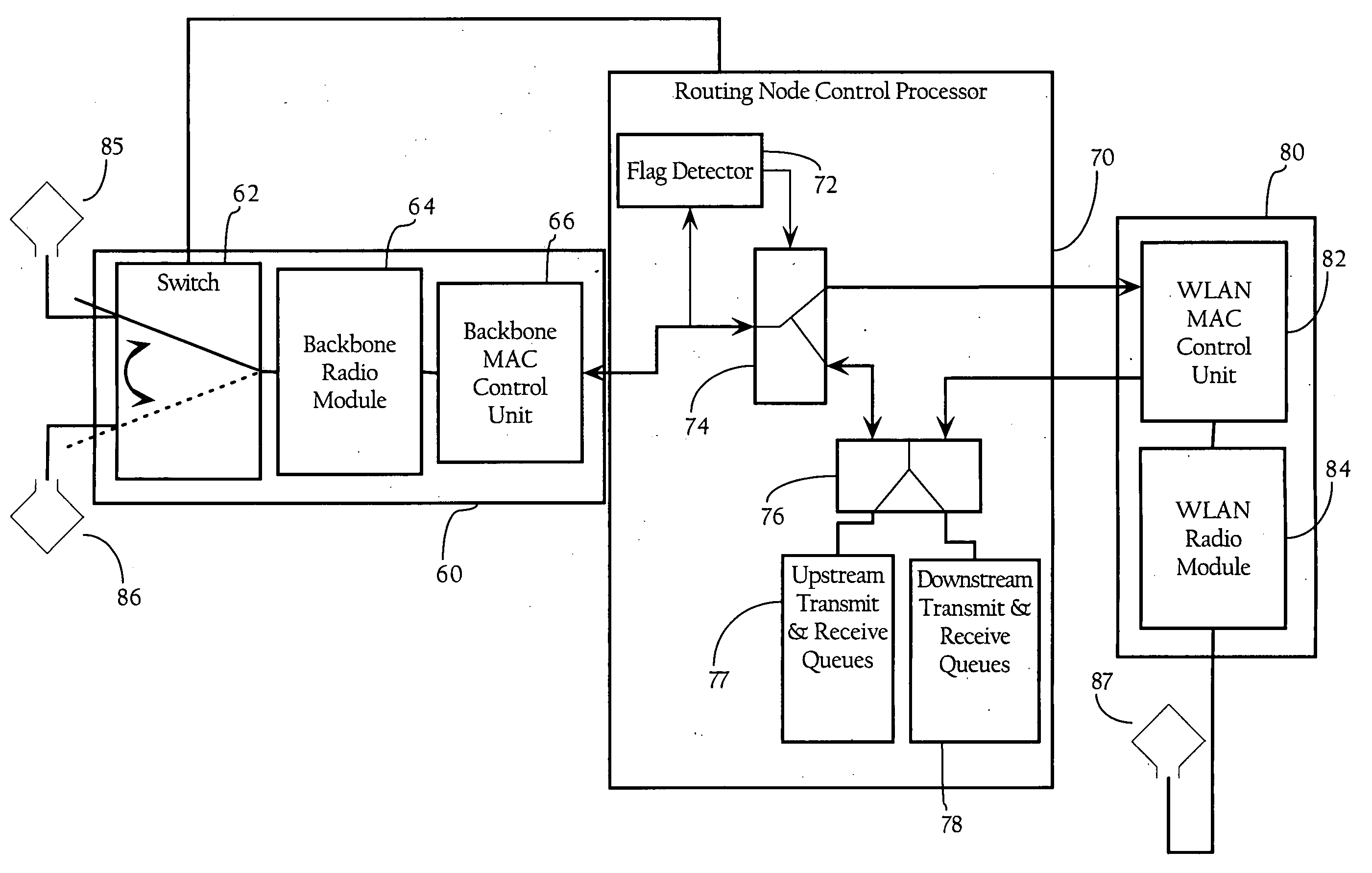
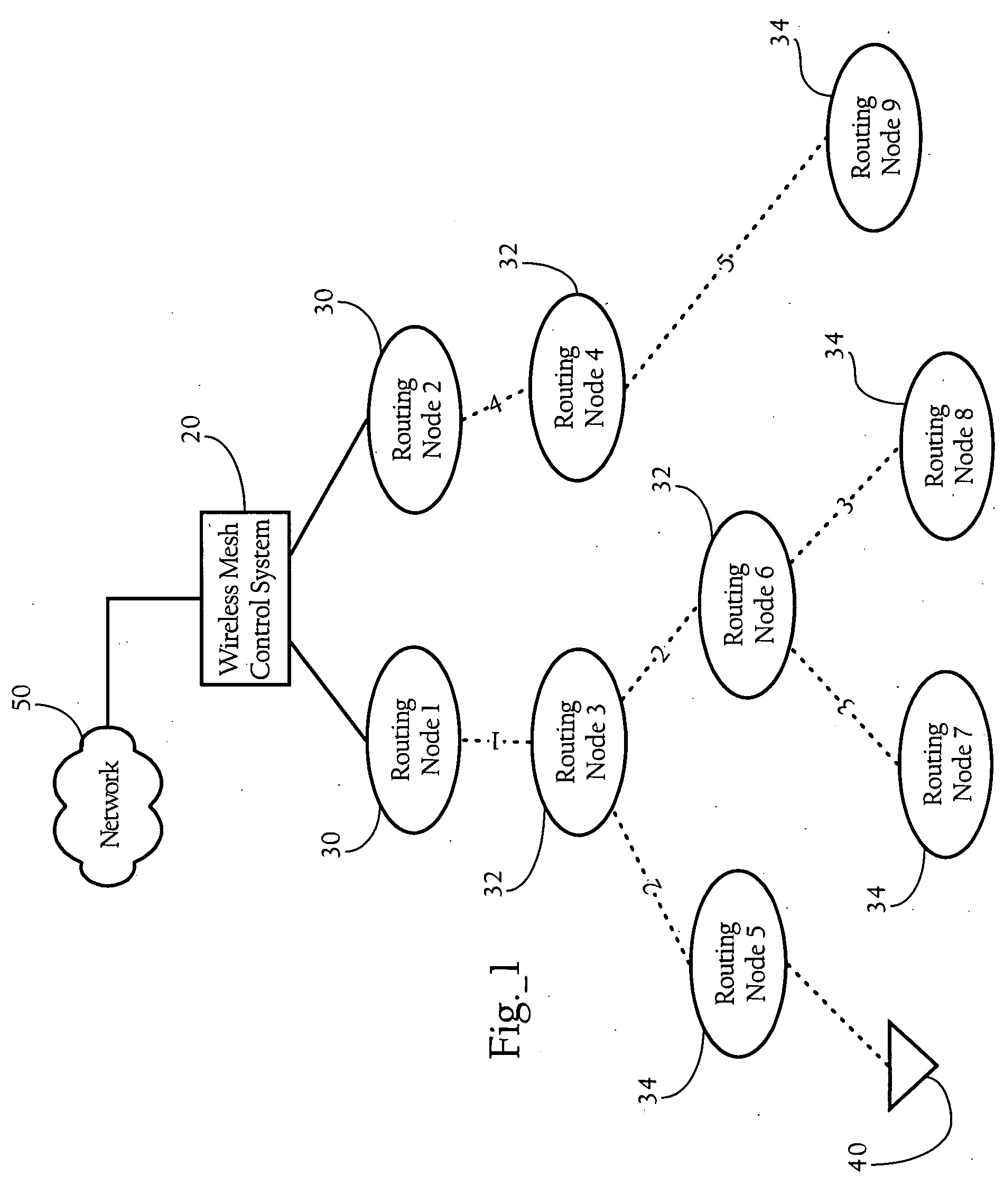
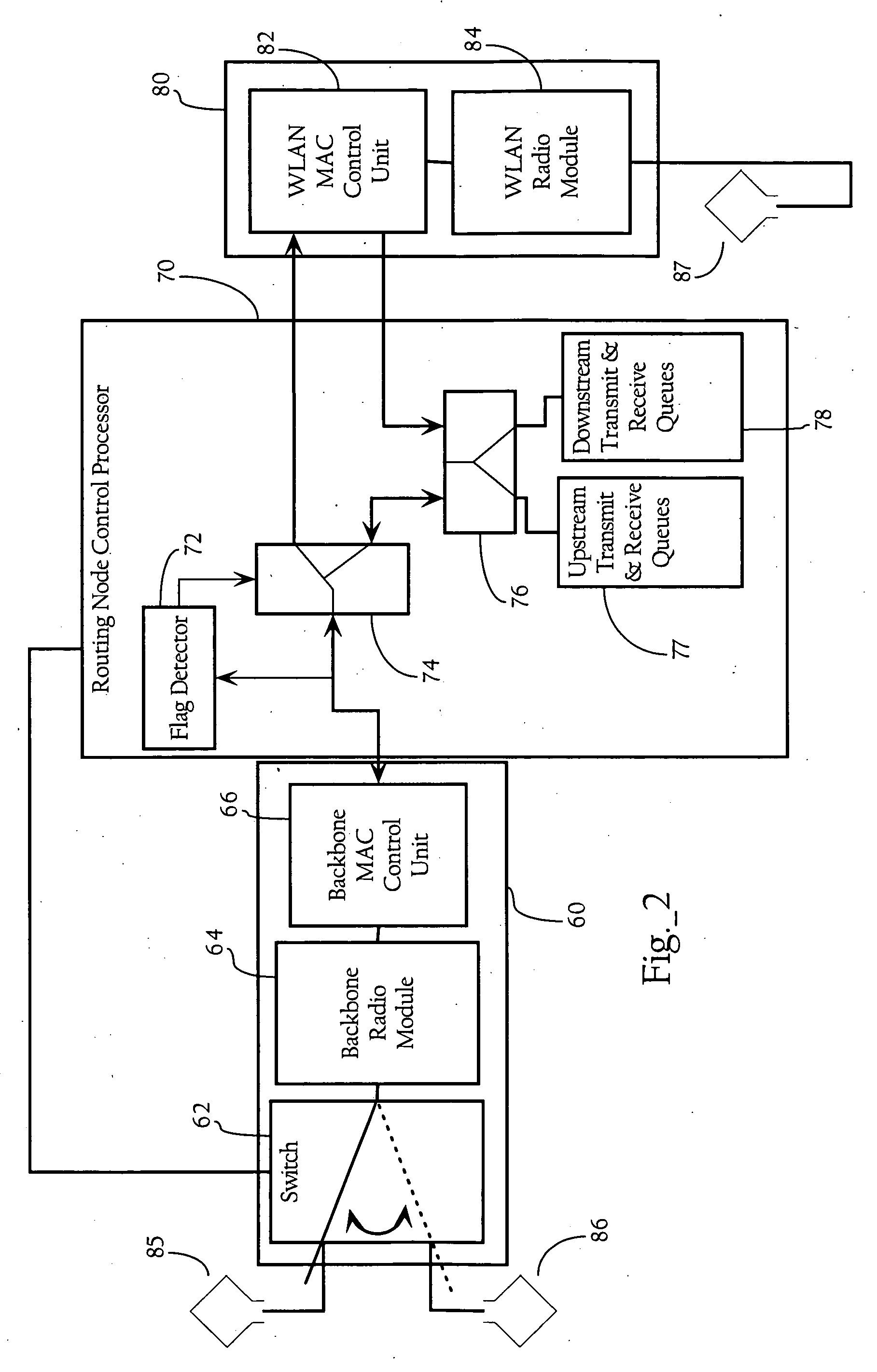
[0015] In one implementation, neighboring routing nodes, or “neighbors,” exchange hello or neighbor messages, which contain a route cost and a hop count associated with the transmitting routing node. Routing nodes use the information contained in these messages to select a route to a root node. As described in more detail below, in one implementation, the route cost advertised by a given routing node is the product of all packet delivery ratios (e.g., QPDR and TPDR) at all hops from the routing node to the root node. As described in more detail below, in one implementation, each routing node independently computes a link cost, which is the local QPDR multiplied by the local TPDR. Furthermore, in one implementation, for each neighbor, a given routing node computes a route cost and a hop count. In one implementation, for each neighbor, a given routing node computes a routing metric, which is based on the computed route cost and hop count, and selects a preferred neighbor as the parent routing node based on the best routing metric. Since each selected neighbor in turn has a selected / preferred neighbor, the cumulative selection process effectively creates a route from a given routing node to the root node. The routing nodes achieve increased end-to-end throughput by selecting parent routing nodes (i.e., preferred neighbors) having optimal hop costs and reduced hop count. As described in more detail below, in one implementation, the route cost, and hop count derived from the route cost and hop count of the selected neighbor becomes the new route cost and new hop count to be advertised in hello messages to other neighbor routing nodes. B. Exemplary Wireless Mesh Network System Architecture

Problems solved by technology

This inflection point has highlighted not only the limitations of earlier-generation systems, but also the changing role that WLAN technology now plays in people's work and lifestyles, across the globe.
While utilizing hop count as a routing metric works well in wired networks, such an approach may suffer from performance degradation in wireless networks, especially in multi-hop wireless mesh networks.
Two factors contribute to such performance degradation: 1) wireless links are versatile and interference is time-varying; and 2) contention based wireless media access control (MAC) protocols introduce uncertainties in the system performance.
If only network layer information such as the hop count is considered, the resulting routing configuration may cause some routing nodes in the mesh to be heavily congested and thus may adversely affect end-to-end throughput.
However, such metrics presently do not include end-to-end packet delivery ratio.
However, one problem with merely using SNR as a routing metric is that it does not take into account inter-hop interference, congestion level, and hop count.
Some routing protocols may combine SNR and hop count but such a combination still does not solve the congestion and interference problem.
A problem with existing routing protocols is that they fail to choose routes with the maximum end-to-end throughput.
For instance, a metric may view a two-hop route with high SNR as better than a one-hop route with medium SNR, but this does not maximize end-to-end throughput.
Furthermore, routing decisions based on SNR are generally approximated by being “too poor” or “good enough.” As such, once the “good enough” SNR state is reached, there is no strong correlation between packet delivery probability and SNR, which in turn implies that SNR may not be a good predictive tool.
However, presumably for implementation ease, the shape of the mapping near the transition region does not closely match the packet delivery probability shape.

Method used


Image

  • Cross-layer design techniques for interference-aware routing configuration in wireless mesh networks
  • Cross-layer design techniques for interference-aware routing configuration in wireless mesh networks
  • Cross-layer design techniques for interference-aware routing configuration in wireless mesh networks

Examples


Embodiment Construction

A. Overview

[0014] The present invention provides methods, apparatuses, and systems directed to facilitating increased throughput in wireless mesh networks. Generally, according to one implementation of the present invention, routing nodes in a wireless network, such as a wireless mesh network, combine metrics corresponding to the link and network layers to select a route to a root node in a wireless mesh network. While the embodiments of the present invention disclose herein are described in the context of hierarchical wireless mesh networks implementing tree-based routing protocols, the present invention may also apply to other types of networks supporting and dynamically configuring paths to destination nodes. In one implementation, each routing node generates link layer metrics and network layer metrics. Link layer metrics are statistics measured at the data link layer and, in one implementation, may include a queued packet delivery ratio (QPDR) and a transmitted packet delivery ...


PUM


Abstract

Methods, apparatuses and systems directed to facilitating increased throughput in wireless mesh networks. Generally, according to one implementation of the present invention, routing nodes in a wireless mesh network combine metrics corresponding to the link and network layers to select a route to a root node in the wireless mesh network. In one implementation, for each neighbor, a given routing node computes a routing metric, which is based on the computed route cost and hop count, and selects a preferred neighbor as the parent routing node based on the best routing metric.

Description

CROSS-REFERENCE TO RELATED APPLICATIONS AND PATENTS [0001] This application makes reference to the following commonly owned U.S. patent applications and / or patents, which are incorporated herein by reference in their entirety for all purposes: [0002] U.S. patent application Ser. No. 10 / 407,584 in the name of Patrice R. Calhoun, Robert B. O'Hara, Jr. and Robert J. Friday, entitled “Method and System for Hierarchical Processing of Protocol Information in a Wireless LAN;” and [0003] U.S. patent application Ser. No. 11 / 213,287 in the name of Neal Dante Castagnoli and Robert J. Friday, entitled “Automatic Route Configuration in Hierarchical Wireless Mesh Networks”FIELD OF THE INVENTION [0004] The present invention relates to wireless networks and, more particularly, to methods, apparatuses, and systems directed to route configuration mechanisms in wireless mesh networks. BACKGROUND OF THE INVENTION [0005] Market adoption of wireless LAN (WLAN) technology has exploded, as users from a wid...

Claims


Application Information

Patent Timeline
IPC IPC(8): H04J3/14H04Q7/24H04W40/12H04W40/16H04W40/30H04W84/22
CPCH04L45/124H04L45/20H04W84/22H04W40/16H04W40/30H04W40/12
Inventor GONG, XIAOHONGHART, BRIAN DONALDDOUGLAS, BRETTON LEE
Owner CISCO TECH INC
Learn More