Additive manufacturing sprayer for fiber reinforced composite material based on ultrasonic enhancing
A reinforced composite material and additive manufacturing technology, applied in the field of additive manufacturing, can solve problems such as easy plugging, fiber cannot be produced, and is in the research and development stage, achieving the effects of quick cleaning, improved printing quality, and enhanced bonding effect
- Summary
- Abstract
- Description
- Claims
- Application Information
AI Technical Summary
Problems solved by technology
Method used
Image
Examples
specific Embodiment approach 1
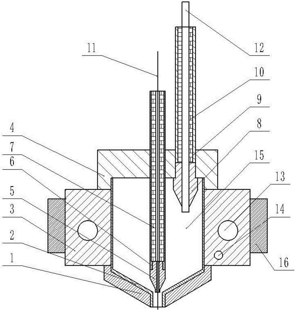
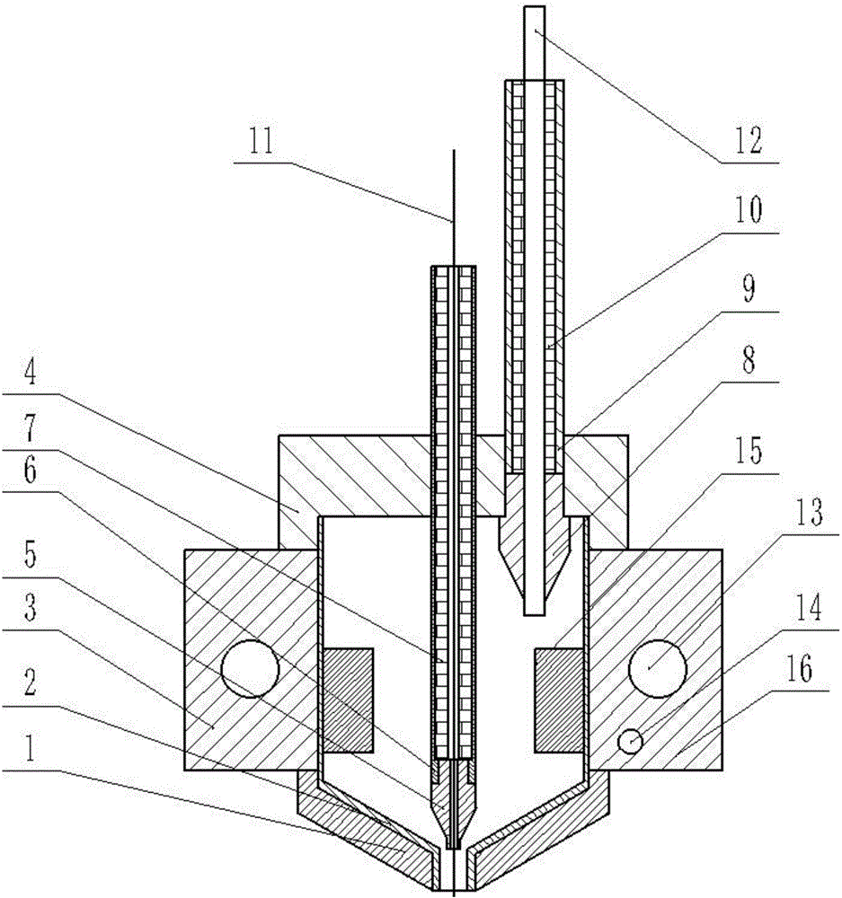
[0031] Combine below figure 1 , 2 , 3 illustrate this embodiment, the present invention belongs to the field of additive manufacturing, more specifically, it relates to a nozzle based on ultrasonically reinforced fiber-reinforced composite material additive manufacturing, including a nozzle 1, an inner cavity 2, a heat conducting block 3, and a cap 4 , fiber nozzle 5, fiber throat 6, Teflon tube Ⅰ 7, resin nozzle 8, resin throat 9, Teflon tube Ⅱ 10, heating rod 13, temperature sensor 14 and ultrasonic generator 16, can improve the relationship between resin and fiber Adhesive effect prevents clogging and facilitates cleaning of nozzles.
[0032] The spray head 1 is detachably connected to the lower end of the inner cavity 2, the heat conduction block 3 is set on the spray head 1, the heat conduction block 3 is nested with a heating rod 13 and a temperature sensor 14, and the upper end of the inner cavity 2 is detachable A cap 4 is attached. The detachable connection can be ...
specific Embodiment approach 2
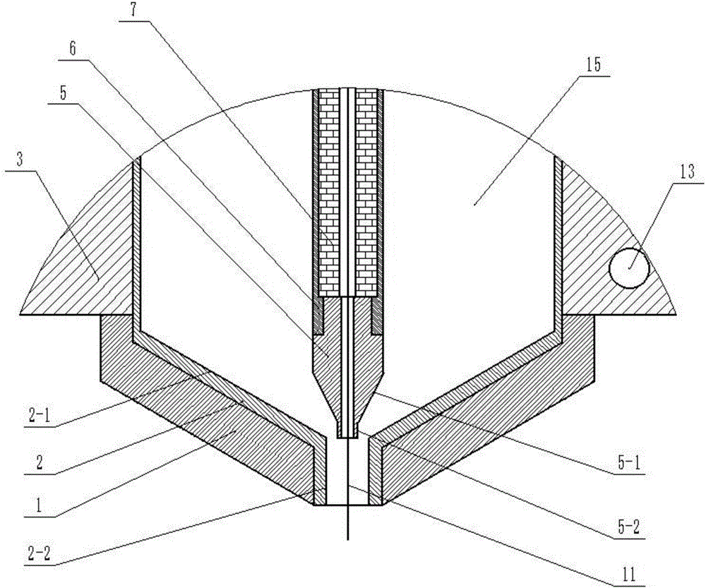
[0039] Combine below figure 1 , 2 , 3. Describe this embodiment. This embodiment will further explain Embodiment 1. The inner chamber 2 includes an inclined section I2-1 and a vertical section I2-2, and the fiber nozzle 5 includes an inclined section II5-1 and a vertical section II5. -2, the inclined section I2-1 of the inner cavity 2 and the inclined section II5-1 of the fiber nozzle 5 form a resin material flow guide cavity whose cross-sectional area decreases sequentially from top to bottom, and the vertical section I2 of the inner cavity 2 -2 forms a cylindrical extrusion cavity, and the vertical section II5-2 of the fiber nozzle 5 forms a cylindrical baffle column. The outlet cross-sectional area of the resin material flow guide cavity is getting smaller and smaller, so that the flow velocity of the resin increases, and the pressure at the outlet increases, so that the bonding effect between the resin and the fiber is better, thereby improving the mechanical properties...
specific Embodiment approach 3
[0041] Combine below figure 1 , 2 , 3 illustrate this embodiment, and this embodiment further describes the first embodiment, the lowermost end of the vertical section II5-2 of the fiber nozzle 5 is located in the vertical section I2-2 of the inner chamber 2. This can effectively ensure that the fiber 11 is in the middle of the resin, thereby improving the printing effect.
PUM
 Abstract
Description
Claims
Application Information
 - R&D
- Intellectual Property
- Life Sciences
- Materials
- Tech Scout
- Unparalleled Data Quality
- Higher Quality Content
- 60% Fewer Hallucinations
Browse by: Latest US Patents, China's latest patents, Technical Efficacy Thesaurus, Application Domain, Technology Topic, Popular Technical Reports.
© 2025 PatSnap. All rights reserved.Legal|Privacy policy|Modern Slavery Act Transparency Statement|Sitemap|About US| Contact US: help@patsnap.com


